What types of modeling do connections generate?
When you associate a Connection Property to a Connection,
finite elements will be automatically generated.
The following table gives you the correspondence between connection
properties and generated finite element.
|
Connection Properties Type |
Connection Property |
Generated Finite Element |
|
Face Face |
||
|
Distant |
||
To know more about finite element, refer to the Elements section in the Finite Element Reference Guide.
What type of property for what type of connection?
When you want to use the connection properties of the Generative Assembly Structural Analysis product, you first need to define a connection that the connection property will reference.
You can apply connection properties on Analysis Connections, Assembly Constraints, Welding Joints or Joint Connections.
To know which connection properties can be applied on the desired connection, refer to the About Connection Properties section.
|
|
Certain connection properties need a few precisions. |
Which property is taken into account by the solver?
If you apply several properties to the same support and then to the same finite element, only the last property created is taken into account by the solver when you launch a computation.
To know which property is taken into account, you can generate an image on the Properties set, edit this image and clear the Do not combine check box in the Image Edition dialog box.
This is an example:
-
Open the sample51.CATAnalysis document.
-
Create two 2D properties with two different thicknesses (1mm for the first one and 2mm for the second one).
-
Perform a Mesh Only computation.
-
Right-click Properties.1 and select Generate Image.
-
Select Thickness fringe in the Image Generation dialog box and click OK.
Both the image and the associated color palette are displayed.

-
Edit the generated image.
-
Click the More>> button, clear the Do not combine check box in the Image Edition dialog box and click OK.
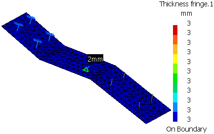
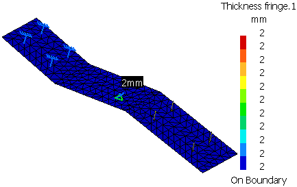
Note that the values of the Thickness fringe.1 image have changed:

The thickness value corresponds to the second 2D property, the one taken into account by the solver.