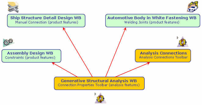
When you want to use the connection properties of the Generative Assembly Structural Analysis product, you first need to define a connection that the connection property will reference.
The connections can be created in different ways:
- in a product context:
- Assembly Constraints in the Assembly Design workbench
- Welding Joints in the Automotive Body in White Fastening workbench
- Joint Connections in the the Ship Structure Detail Design workbench (Manual Connection command)
- Analysis Connections created before V5R12

The former Analysis Connections are still maintained but:
-
You cannot create them any longer.
-
You cannot select them as Connection Properties support any longer.
It is strongly recommended to migrate the Analysis Connections created before V5R12.
To do this, refer to Checking the Model.
-
- in an analysis context:
- Analysis Connections in the Generative Structural Analysis workbench (from V5R12)

Why you will use Connections of the Analysis Workbench?
In some cases, constraints are not sufficient to modelize connections from an Analysis viewpoint:
-
In order to support properties, users often need to define too many constraints using the Assembly Design workbench, leading to over-constrained models that cannot be updated.
-
It is impossible to define constraints that are not positioning constraints but connection constraints.
-
It is impossible to select several geometries to define connections in a product context.
-
It is impossible to select a mechanical feature to define connections in a product context.
In order to meet these different needs, a new Analysis
Connection toolbar was added to the Generative Assembly Structural
Analysis product of the Generative Structural Analysis workbench.
This toolbar lets you create all these connections dedicated to analysis
modeling.
What Type of Hypotheses are Used for Analysis?
You will find here below three types of hypotheses used when working in Analysis workbench.
- Small displacement (translation and rotation)
- Small strain
- Linear constitutive law: linear elasticity
For static case solutions, one can say that:
- If there is no contact feature (either virtual or real), no pressure fitting property and no bolt tightening (being virtual or not) feature, then the problem is linear, that is to say, the displacement is a linear function of the load.
- In other cases, the problem is non linear, that is to say, the displacement is a non linear function of the load.
What Type of Property For What Type of Connection?
Welding Connections Properties
- Spot Welding Connection Property:
- Point Analysis Connection defined in the Generative Structural Analysis workbench (from V5R12)
- Point Analysis Connection within one Part defined in the Generative Structural Analysis workbench (from V5R12)
- Joint Body containing at least a (point) Joint Element and defined in the Body in White Fastener workbench
- Seam Welding Connection Property:
- Line Analysis Connection defined in the Generative Structural Analysis workbench (from V5R12)
- Line Analysis Connection within one Part defined in the Generative Structural Analysis workbench (from V5R12)
- Joint Body containing at least a (line) Joint Element and defined in the Body in White Fastener workbench
- Surface Welding Connection Property:
- Surface Analysis Connection defined in the Generative Structural Analysis workbench
- Surface Analysis Connection within one Part defined in the Generative Structural Analysis workbench
Other Connection Properties
When you define a connection property, you can select as support:
- General Analysis Connection of the Generative Structural Analysis workbench (from V5R12)
- Assembly Constraints (Contact Constraint, Coincidence
Constraint or Offset Constraint) of the Assembly
Design workbench
General Analysis Connection (from V5R12)
| Connection Properties | Point / Point | Point / Lines* | Point / Faces* | Lines* / Lines* | Lines* / Faces* | Faces* / Faces* |
| Slider |
|
|||||
| Contact |
|
|||||
| Fastened |
|
|
|
|
|
|
| Fastened Spring |
|
|
|
|
|
|
| Pressure Fitting |
|
|||||
| Bolt Tightening |
|
|
|
|
|
|
| Rigid |
|
|
|
|
|
|
| Smooth |
|
|
|
|
|
|
| Virtual Rigid Bolt Tightening |
|
|
|
|
|
|
| Virtual Spring Bolt Tightening |
|
|
|
|
|
|
| User-Defined |
|
|
|
|
|
|
*
You can multi-select:
** with optional handler point: the selection of a general analysis connection with a handler point is forbidden for all the other combinations (the pointer indicates what you can select or not). |
||||||
Assembly Constraints
By default, you can select any assembly constraints as Connection Property support.
Former General Analysis Connections and Face Face Analysis Connections (before V5R12)
|
|
You cannot select these connections as Connection
Properties support any longer. |
Precisions and Restrictions
|