Mechanical Modeler |
Creating a New Geometrical Feature: the Combined CurveA full example to create and integrate in the V5 your own geometrical features |
|
| Use Case | ||
AbstractThis use case explains how to create and integrate a new geometrical feature into CAA V5: the Combined Curve. |
This use case illustrates the sub-section entitled "Creating a New Mechanical Feature" that you can see in the "Technical Articles" section of the Mechanical Modeler home page. Its main intent is to help you to make your first steps in creating a new geometrical feature. A geometrical feature being a mechanical feature with a geometrical result [1].
You will learn to:
How to create a new StartUp, how to store it in a feature's catalog and how to instantiate it. For this part, you can you refer to the "Creating a New StartUp Deriving from a Mechanical StartUp" technical article [2] for details.
A feature is completely described by a set of behaviors, in other words interfaces. Some are inherited from the mechanical feature StartUp, but some need to be implemented. Among them, there are the mandatory interfaces (CATIBuild for example) and the Dassault Systèmes behavior interfaces to be fully integrated in the V5. The technical article entitled "Integrating a New Mechanical Feature in V5" give you an overview of these interfaces [3].
The Combined Curve use case forms a set of articles, each describing the creation or the integration. All of these articles illustrate how to integrate some components coming from various V5 frameworks, such as the Feature Modeler framework, the Geometric Modeler frameworks or the Dialog and DialogEngine frameworks. Their intent is to focus on the use of the three main V5 Mechanical Applications platform frameworks : MechanicalModeler, MechanicalModInterfaces and MechanicalModelerUI. A prerequisite knowledge of other frameworks may be required to fully understand this use case, some links with other CAA V5 use cases will help you navigate among them.
Before getting to the use case, it is important to get an understanding of what a Combined Curve is. This is the goal of the next section. You can skip it if you are already familiar with this concept.
[Top]
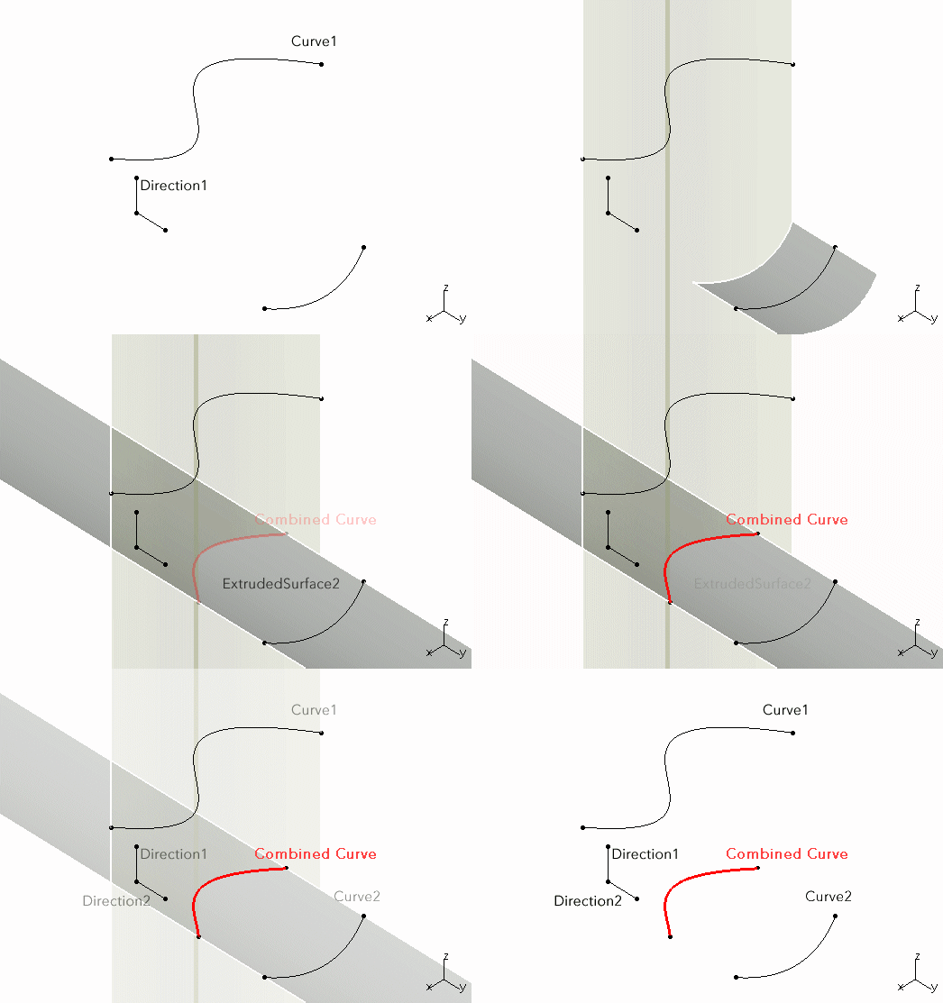
A Combined Curve is a curve resulting of the intersection of two surfaces, each of them being extruded from a curve along a direction.
Consequently, a Combined Curve has two input curves also named profiles and two input directions.
 |
The two extruded surfaces are only temporary hidden support objects.
[Top]
The Combined Curve is a use case of the CAAMechanicalModeler.edu framework that illustrates MechanicalModeler, MecModInterfaces and MechanicalModelerUI framework capabilities.
[Top]
The final intent of this use case is to create a wireframe feature of the Shape Design Workbench. It can be divided into several steps:
Here is an image of the "CAAMmrCombinedCurveCatalog" feature's catalog containing the CombinedCurve StartUp. You can note the input specifications: two curves and two directions, four features.
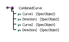 |
The CombinedCurve is a mechanical feature and more precisely a geometrical feature, so the StartUp hierarchy is the following:
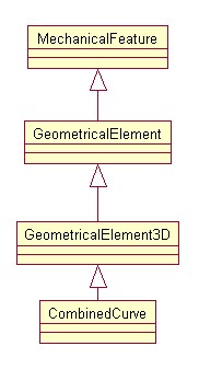 |
To create instances of the CombinedCurve StartUp, you should create and implement a factory interface on the specification container [8]. This interface creates a new instance but do not set the newly instance in a geometrical features set [7].
 |
CATPrtCont is the container containing all the specifications of the Part document. This factory interface uses the "CAAMmrCombinedCurveCatalog" catalog file created in the first step.
In the CATIBuild implementation, or in the Combined Curve edition command, it is mandatory to have an access to the input specifications of the new feature. It is the role of the CAAIMmrCombinedCurve interface.
 |
With this interface you can retrieve or modify the two curves and the two directions.
The technical article [3] explains that for a feature deriving from the GeometricalElement3D StartUp - Fig.3 - the interfaces to take into account to integrate it in the V5 can be classified in three cases:
The mandatory interfaces
This interface enables you to build the result of the feature. Reading this technical article [4] is strongly recommended before getting to the use case.
This interface enables you to define the available elements for a replacement, and makes the replacement. The easiest way to implement it is to use its adaptor class, and to delegate to the CATIAttrBehavior interface the way to define the available elements.
This interface enables you specify that the CombinedCurve StartUp is a surfacic feature. Without this implementation, you will have wrong behaviors for instances aggregated in a solid and surfacic features set.
This interface enables you to aggregate the instances of the CombinedCurve StartUp into ordered sets: in other words: Ordered Geometrical Set features and Body features.
The Dassault Systèmes Behavior interfaces
This interface enables you to manage the build's activation status of the combined curve. The CATIBuild implementation takes the activation status of the combined curve into account before generating the result. Interactively you can propose to the end user to choose the state, if you insert a switch into the contextual menu; It will be explained in the Adding a Contextual Sub-Menu
This interface of the ApplicationFrame framework enables editing a
Combined Curve instance. It launches the CAAMmrCombCrvPanelStCmd
state dialog command. This command can be used in the creation mode
and in the edition mode. For this last mode, refer to the "Creating
Interactively Instances" step.
The CAAMmrCombCrvPanelStCmd state dialog command uses a dialog box to help the
end user enter/modify the input.
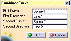 |
This interface of the ApplicationFrame framework enables you to add commands after the Definition command. This command is in the sub-menu of the contextual menu associated with the Combined Curve.
 |
This use case explains how to implement this interface and how to retrieve Dassault Systèmes (or other) commands.
These three interfaces enables you to integrate Combined Curves instances in a component catalog. Refer to the technical article [5] for details.
 |
For specific case interfaces
See the Modifying Combine's Curve Specifications article.
The MechanicalFeature feature - Fig.1- already implements the CATIIcon interface. For a simple case as the Combined Curve, you have only to provide an icon whose name is : I_StartUpName.bmp where StartUpName is the name of the StartUp. In the CNext/Resources/graphic directory of the CAAMechanicalModeler.edu framework, you will thus find the I_CombinedCurve.bmp file.
In short, the Combined Curve, deriving from a mechanical StartUp, benefits from mechanical behaviors, but it should or could implement other interfaces to be fully integrated in V5. The following interfaces are explained in this use case:
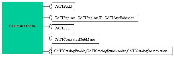 |
The last three interfaces, CATICatalogEnable, CATICatalogSynchronize, CATICatalogInstantiation, being advanced interfaces, their implementations are not required for a first step.
To create new instances of the Combined Curve, you will create an add-in of the Shape Design workbench into which you will add the Combined Curve Creation command. Creating an Add-in in the Shape Design Workbench
[Top]
The documentation of the Combined Curve use case contains the following articles:
Creating Combined Curve's Catalog. This article describes the creation of the catalog containing the new feature StartUp definition.
Creating Combined Curve's Factory Interface. This article describes the creation and the implementation of the new feature factory interface.
Creating Combined Curve's Interface of Type. This article describes the creation and the implementation of the interface which enables you to retrieve or modify the input specifications of the new feature.
Building Combined Curve's Result. This article describes the implementation of the CATIBuild interface on the new feature.
Enabling Combined Curve's Result Deactivation. This article describes the implementation of the CATIMechanicalProperties interface on the new feature.
Integrating Combined's Curve inside Ordered Sets. This describes the implementation of the CATInputDescription interface on the new feature.
Defining Combined's Curve Type. This describes the implementation of the CATIMf3DBehavior interface on the new feature.
Verifying the Combined Curve's Sub-Element Selectability. This article describes how to create an Add-in of the Part workshop and how to use a mechanical command to verify that each cell of the topological result, built by the CATIBuild interface, is selectable.
Modifying Combine's Curve Specifications. This article describes the implementation of the replace mechanism on the new feature.
Editing Combined. This article describes editing the new feature through a dialog box and implementing the CATIEdit interface.
Adding a Contextual Sub-Menu. This article describes the CATIContextualSubMenu interface implementation
Creating an Add-in in the Shape Design Workbench. This article describes creating an Add-in of the Shape Design workbench to insert the new feature creation command.
Integrating a New Type of Component. This article describes integrating a new feature in a component catalog.
[Top]
To launch the Combined Curve use case, you will need to set up the build time environment, then compile the following modules of the CAAMechanicalModeler.edu framework along with their prerequisites:
Next, execute the use case [6]. Several steps must be followed in order to completely execute the use case:
where
mkrun -c "CAAMmrCreateCombCrvCatalog CatalogPath"CatalogPathis the path of the directory in which the "CAAMmrCombinedCurveCatalog.CATFct" file will be created. It is recommended that the new catalog be stored in the CNext + resources + graphic directory of the current framework; then, by updating the runtime view, the catalog will be moved to the runtime directory and will be accessible by subsequent programs.
mkrun -c "CAAMmrCombinedCurveSample FileName"
where FileName is the saved name (with or without the CATPart
suffix) of
the Part created by this command. The created Part document contains one
Combined Curve. A "CAACombinedCurve.CATPart" file is stored in
the InputData directory of the CAAMechanicalModeler.edu framework.
Launch CATIA. When the application is ready, follow scenarios described below:
The Creation scenario:
The Edition scenario
The Contextual-SubMenu scenario
Once the Combined Curve is created, try the Replace scenario:
For the Component Catalog Integration scenario:
- On the File menu click Open
- in the File Selection dialog box retrieve the CAACombinedCurve.CATPart (*) document and click Open
- On the File menu click New
- In the File New Dialog box select CatalogDocument and click OK
- Launch the Add Family
command
- In the Component Family Definition dialog box, enter Family in the Name field and click OK
- Select Family in the specification tree
- Launch the Keyword
command
- In the Keyword Definition dialog box
- Enter Inputs number in the Name field
- Select Integer as Type
- Click OK
- Launch the Add Component
command
- In the Description Definition dialog box
- Push Select external feature
- select the CombineCrv in the Part document
- Click OK
(*) The file is located in the directory
CAAMechanicalModeler.edu/InputData
- Unix :
InstallRootDirectory/CAAMechanicalModeler.edu/InputData- Windows :
InstallRootDirectory\CAAMechanicalModeler.edu\InputDatawhere
InstallRootDirectoryis the directory where the CAA CD-ROM is installed.
[Top]
The Combined Curve use case is made of a several modules of the CAAMechanicalModeler.edu framework:
| Windows | InstallRootDirectory\CAAMechanicalModeler.edu\ |
| Unix | InstallRootDirectory/CAAMechanicalModeler.edu/ |
where InstallRootDirectory is the directory where the CAA CD-ROM
is installed.
These modules are:
[Top]
You can now successively get to:
[Top]
The CAAMechanicalModeler.edu Combined Curve Sample shows how to create your own geometrical Feature.
[Top]
| Version: 1 [Mar 2000] | Document created |
| Version: 2 [Jan 2003] | Document updated |
| Version: 3 [Jan 2005] | Document updated for CATIMechanicalProperties introduction |
| [Top] | |
Copyright © 2000, Dassault Systèmes. All rights reserved.