Mechanical Modeler |
Editing Combined CurvesImplementing CATIEdit through a dialog box and a state dialog command |
|
| Use Case | ||
|
Creating a New Geometrical Feature : The Combined Curve > Editing Combined Curves |
||
AbstractThe main goal of this use case is to describe how to edit Combined Curves interactively. |
This use case explains how to edit Combined Curves interactively. You will learn to:
Moreover, the state command can be also used to create new instances. Consequently, this article gives you also explanations to create a command to instantiate Combined Curves interactively. However, to light the article, the piece of code which makes the instantiation has been off-set in the referenced article [1].
The use case intent is to help you make your first step in the interactive edition world. Some more sophisticated examples are provided with Dialog and DialogEngine frameworks. The point of this use case is to show an example of an edition command taking full advantage of services provided by Mechanical Modeler Frameworks.
[Top]
CAAMmrCombinedCurveUI is a use case of the CAAMechanicalModeler.edu framework that illustrates MechanicalModeler framework capabilities.
[Top]
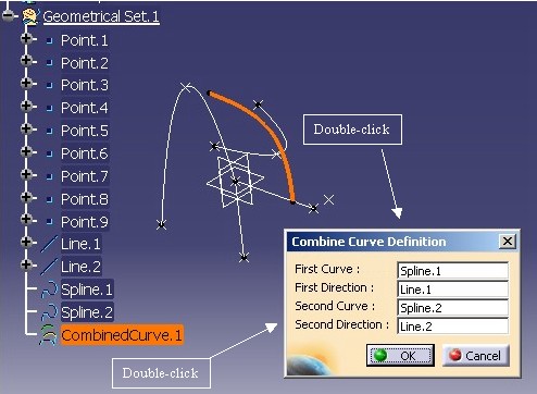
The CAAMmrCombinedCurveUI use case enables you to edit an existing combined
curve through a state command and a dialog box. Here is a picture showing the
edition of the combined curve included in the CAACombinedCurve.CATPart
document. This file is located in the InputData directory of the
CAAMechanicalModeler.edu framework.
 |
The next figure summarizes the architecture of the Combined Curve edition pattern.
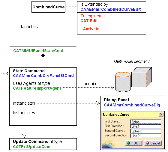 |
The CATIEdit interface links the Combined Curve to its edition state dialog command, called CAAMmrCombCrvPanelStCmd. This command can make the creation or the modification of an instance.
This command derives from CATMMUIPanelStateCmd to benefit from command edition standard behaviors.
It uses specific import agents of type CATFeatureImportAgent to acquire geometry in a multi-model context, and instantiates a dialog box that recounts the Combined Curve's input modifications.
[Top]
The CAAMmrCombCrvPanelStCmd command class has been modified in V5R13 to take the ordered set [2][3] into account. There are three main modifications:
Current feature management
The specifications are the following:
(*) In the CAAMmrCombCrvPanelStCmd command the new feature is created at the end of the command, but generally the creation is done at the beginning. In the first case, the feature is set current at the end of the command, otherwise it stays current at the end.
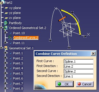 |
On this above picture CombinedCurve.2 is into an ordered set (an Ordered Geometrical Set). When it is being edited, you can
see that it is the current feature since it is underlined.
The management of the current feature has been processed by the Overriding Activate, Deactivate and Cancel methods to Manage Current Feature section.
When aggregating a feature into an ordered set you should take care of the position of the current feature. The new feature is located after the current feature. This management, specific to the creation mode, is detailed in the referenced article [1] which deals with the instantiation of the combined curve.
When a geometrical feature [4] is inserted into
an ordered set, or when a surfacic feature [4] is
modified into a such set, you must call the Insert method of the CATMmrLinearBodyServices
class. This call has been integrated just after the update of the combined
curve, in the OkAction method.
[Top]
See the section entitled "How to Launch the Combined Curve Use Case" in the "Creating a New Geometrical Feature: The Combined Curve" use case for a detailed description of how this use case should be launched.
[Top]
The CAAMmrCombinedCurveUI use case is made of a several classes located in the CAAMmrCombinedCurveUI.m module of the CAAMechanicalModeler.edu framework:
| Windows | InstallRootDirectory\CAAMechanicalModeler.edu\CAAMmrCombinedCurveUI.m\ |
| Unix | InstallRootDirectory/CAAMechanicalModeler.edu/CAAMmrCombinedCurveUI.m/ |
where InstallRootDirectory is the directory where the CAA CD-ROM
is installed.
The code for this use case is made of the following classes:
[Top]
The CAAMmrCombinedCurveUI is divided into the following steps:
[Top]
As usual, to implement an interface you first need to use the TIE macro.
CATImplementClass ( CAAEMmrCombinedCurveEdit ,
                    DataExtension ,
                    CATIEdit ,
                    CombinedCurve );

CATImplementBOA(CATIEdit, CAAEMmrCombinedCurveEdit);
|
The CATImplementClass macro is used in conjunction with the
CATDeclareClass macro in the class header file to express that the
class is part of a CAA V5 Object Modeler component. Its argument read as follows:
DataExtension: the CAA V5 Object Modeler class type. CATIEdit: The name of implemented interface CombinedCurve: the name of the extended component The CATImplementBOA macro replaces the TIE_CATIEdit
macro. Its arguments are the BOA-implemented interface and the extension class
name respectively.
[Top]
The method Activate of the interface CATIEdit is called
whenever the user shows his willingness to edit a feature, for example when
double clicking on a feature node in the feature tree. It returns a pointer on a
CATCommand. This CATCommand (here called CAAMmrCombCrvPanelStCmd)
is the feature edition command.
...
CATCommand * CAAEMmrCombinedCurveEdit::Activate(CATPathElement *ipPath)
{
  // Gets a pointer on CAAIMmrCombinedCurve in edition
  CAAIMmrCombinedCurve* piCombinedCurve = NULL;
  HRESULT rc = QueryInterface(IID_CAAIMmrCombinedCurve,
                              (void**) &piCombinedCurve);
  if ( FAILED(rc) )
    return NULL;

  // Creates the edition command
  CATCommand *pCommand = new CAAMmrCombCrvPanelStCmd(piCombinedCurve);

  // Releases useless pointer
  piCombinedCurve->Release();
  piCombinedCurve = NULL ;

  return pCommand;
}
|
[Top]
#include "CATCreateExternalObject.h" CATCreateClass(CAAMmrCombCrvPanelStCmd); |
These two lines enables the frame to launch the command thanks to an header of command.
[Top]
The Combined Curve edition/creation state dialog command constructor:
CAAMmrCombCrvPanelStCmd::CAAMmrCombCrvPanelStCmd
                                       (CAAIMmrCombinedCurve *ipiCombinedCurve)
                       : CATMMUIPanelStateCmd("CombinedCurveCommand")
|
This derivation is very helpful, since it provides several default behaviors you will not have to implement by yourself.
...
_mode = 0 ;
if ( NULL != ipiCombinedCurve )
{
   _mode = 1 ;
   ...
...
|
_mode is a data member of CAAMmrCombCrvPanelStCmd,
and returned by the GetMode method - see the Overriding Methods from the Parent Command
CATMMUIPanelStateCmd section.
... rc = ipiCombinedCurve->GetCurve(1, &_piSpecOnCurve1); if ( FAILED(rc) ) return ; rc = ipiCombinedCurve->GetDirection(1, &_piSpecOnDir1); if ( FAILED(rc) ) return ; rc = ipiCombinedCurve->GetCurve(2, &_piSpecOnCurve2); if ( FAILED(rc) ) return ; rc = ipiCombinedCurve->GetDirection(2, &_piSpecOnDir2); if ( FAILED(rc) ) return ; ... |
Thanks to CAAIMmrCombinedCurve, it is very easy to ask the Combined Curve its input curves and directions. You do not have to worry about the details of the Combined Curve feature implementation [7].
This part is done only in edition mode, when ipiCombinedCurve is not null.
This Combined Curve edition dialog box is very basic. A description of this dialog box's code is available below. See the Creating the Combined Curve Edition Dialog Box section.
... _panel = new CAAMmrCombinedCurveDlg(); _panel->Build(); UpdatePanelFields(); ... |
The build of a dialog box must be always outside the dialog class constructor. The names of the Combined Curve input curves and directions appear in the dialog box fields in case of edition Fig.1, otherwise the "noselection" string appears.
[Top]
The BuildGraph method describes how the command works.
_pCurveAgent     = new CATFeatureImportAgent("CurveAgent",      NULL,
                                             NULL, MfNoDuplicateFeature) ;
_pDirectionAgent = new CATFeatureImportAgent("DirectionAgent" , NULL ,
                                             NULL, MfNoDuplicateFeature) ;
|
// _pCurveAgent to select a curve
_pCurveAgent -> SetOrderedElementType ( "CATIMfMonoDimResult" );
_pCurveAgent -> AddOrderedElementType ( "CATCurve"            );
_pCurveAgent -> AddOrderedElementType ( "CATEdge"             );
_pCurveAgent -> AddOrderedElementType ( "CATWire"             );
_pCurveAgent -> SetBehavior      ( CATDlgEngWithPrevaluation |
                                   CATDlgEngWithCSO          |
                                   CATDlgEngOneShot           );
_pCurveAgent -> SetAgentBehavior ( MfPermanentBody           |
                                   MfLastFeatureSupport      |
                                   MfRelimitedFeaturization   );
|
This acquisition agent will first look for any objects implementing CATIMfMonoDimResult, then CATCurve, etc.
CATFeatureImportAgent.h Documentation details the possible options.
//-----------------------------------------------------------------------------
// Command States
//-----------------------------------------------------------------------------

// Uses "PanelStates" instead of standard "DialogStates".
// Theses states are provided by father class CATMMUIPanelStateCommand.
// They make it possible for you not to worry about transition to
// OK and Cancel States.

// Curve selection state
CATDialogState *WaitForCurveState= GetInitialPanelState
                               ("Select a curve or another input field");
WaitForCurveState -> AddDialogAgent ( _pCurveAgent           );
WaitForCurveState -> AddDialogAgent ( _pDirection1FieldAgent );
WaitForCurveState -> AddDialogAgent ( _pDirection2FieldAgent );
WaitForCurveState -> AddDialogAgent ( _pCurve1FieldAgent     );
WaitForCurveState -> AddDialogAgent ( _pCurve2FieldAgent     );

// Direction selection state
CATDialogState *WaitForDirectionState= AddPanelState
                            ("Select a direction or another input field");
WaitForDirectionState -> AddDialogAgent ( _pDirectionAgent       );
WaitForDirectionState -> AddDialogAgent ( _pCurve1FieldAgent     );
WaitForDirectionState -> AddDialogAgent ( _pCurve2FieldAgent     );
WaitForDirectionState -> AddDialogAgent ( _pDirection1FieldAgent );
WaitForDirectionState -> AddDialogAgent ( _pDirection2FieldAgent );

//-----------------------------------------------------------------------------
// Transitions
//-----------------------------------------------------------------------------

// From Curve to Curve ( click on several curves to change of curve )
AddTransition ( WaitForCurveState , WaitForCurveState ,
                IsOutputSetCondition ( _pCurveAgent ) ,
                Action ( ( ActionMethod ) &CAAMmrCombCrvPanelStCmd::CurveSelected ) );
...
|
Deriving from CATMMUIPanelStateCmd requests to call GetInitialPanelState
instead of GetInitialState and AddPanelState
instead of AddState.
Here is a figure representing the four possible states of this command and their transitions.
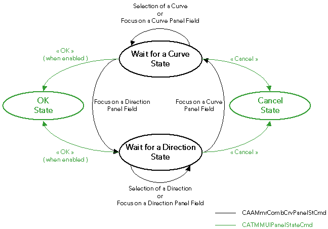
Note: thanks to parent command class CATMMUIPanelStateCmd (green), you only have to code two of them (black).
_pCurve1FieldAgent     -> AcceptOnNotify ( _panel->GetField(1) ,
                                      _panel->GetField(1)->GetListSelectNotification() );
_pCurve2FieldAgent     -> AcceptOnNotify ( _panel->GetField(3) ,
                                      _panel->GetField(3)->GetListSelectNotification() );
_pDirection1FieldAgent -> AcceptOnNotify ( _panel->GetField(2) ,
                                      _panel->GetField(2)->GetListSelectNotification() );
_pDirection2FieldAgent -> AcceptOnNotify ( _panel->GetField(4) ,
                                      _panel->GetField(4)->GetListSelectNotification() );
|
[Top]
This method is called when users press on the OK button of the Combined Curve edition dialog box. Transitions to this OK state are provided by parent Command CATMMUIPanelStateCmd.
In case this edition command is used to modify a Combined Curve, it just modifies the Combined Curve’s input Curves and Direction.
// edition mode // Updates the combine with its new curves inputs. HRESULT rc; rc = _piCombinedCurve -> SetCurve ( 1 , _piSpecOnCurve1 ); if ( FAILED(rc) ) return FALSE; rc = _piCombinedCurve -> SetDirection ( 1 , _piSpecOnDir1 ); if ( FAILED(rc) ) return FALSE; rc = _piCombinedCurve -> SetCurve ( 2 , _piSpecOnCurve2 ); if ( FAILED(rc) ) return FALSE; rc = _piCombinedCurve -> SetDirection ( 2 , _piSpecOnDir2 ); if ( FAILED(rc) ) return FALSE; |
When this command is used to create a new Combined Curve (creation mode), first it retrieves a geometrical features set, and then aggregates the new feature inside the set. The explanations of these two steps have been off-set in the referenced use case [1].
Whatever the command mode (creation or edition), the OKaction
method updates the Combined Curve. To do so, it creates a new update
command of type CATPrtUpdateCom. This command updates only the combined
curve (in manual update mode) or the whole part (automatic update mode). This
command encapsulates interactive error management ( edit / delete, etc...).
...
CATPrtUpdateCom *pUpdateCommand =  new CATPrtUpdateCom (
                        piSpecOnCombinedCurve ,  // the feature to update, translated into part->update
                                                 // in	 case of automatic update setting
                        1                     ,  // respects update interactive setting
                                                 // ( manual / automatic )
                        GetMode()            );  // creation or modification. Prevents the user from
                                                 // creating a feature in error
|
After the update step, if the feature is inside an ordered set,
whatever the command mode (creation or edition), you must call the Insert
method of the CATMmrLinearBodyServices class.
CATBaseUnknown_var spBUOnCC = piSpecOnCombinedCurve ; rc = CATMmrLinearBodyServices::Insert(spBUOnCC); |
The last step consists in to modify the graphic properties of the new combined curve. The graphic properties are changed by this way:
CATIVisProperties *piGraphPropOnCombinedCurve = NULL;
rc = piSpecOnCombinedCurve->QueryInterface( IID_CATIVisProperties,
                                                        (void**)& piGraphPropOnCombinedCurve);

CATVisPropertiesValues Attribut;
Attribut.SetColor(255, 255, 0); // yellow
Attribut.SetWidth(4);           // medium thickness
piGraphPropOnCombinedCurve->SetPropertiesAtt(Attribut, CATVPAllPropertyType, CATVPLine);
|
[Top]
CATBoolean CAAMmrCombCrvPanelStCmd::CancelAction(void *)
{
    if (_editor) _editor -> UnsetRepeatedCommand();
    return TRUE ;
}
|
This code enables you to unset the repeat mode when the Cancel or Close icon are pushed by the end user.
[Top]
The management of the current feature, a specificity of an ordered set, has been implemented through the Activate, Deactivate, and Cancel methods of the CATCommand class [8].
This method is called when the command takes the focus. In this step, if the edited feature is into an ordered set, the current feature is kept, and the edited feature is set the current one.
CATStatusChangeRC CAAMmrCombCrvPanelStCmd::Activate (CATCommand * iCmd,
                                                     CATNotification * iNotif)
{
    if ( (NULL!= iNotif) && (0 == GetMode()) && (NULL !=_piCombinedCurve) )
    {
       CATBoolean IsInsideOrderedBody = FALSE ;
       HRESULT rc = IsCombCrvInsideOrderedBody(IsInsideOrderedBody );
       if ( SUCCEEDED(rc) && (TRUE == IsInsideOrderedBody ) )
       {
...
|
The first part consists in to check the edition mode (GetMode=0),
and in case of edition mode, check the type of the set
aggregating the combined curve (IsCombCrvInsideOrderedBody).
Once the two checks are done, you can keep the current feature and set the edited combined curve as the current one.
...
          if (((CATStateActivateNotification *) iNotif) -> GetType()
                 ==  CATStateActivateNotification::Begin)
          {
             _spSpecObjOnPreviousCurrentFeat = GetCurrentFeature();
          }
...
|
If it is the first activation, the current feature is kept to be restored at
the end of the command, or when the command is deactivated. _spSpecObjOnPreviousCurrentFeat
is a data member of the CAAMmrCombCrvPanelStCmd class. It is initialized
with GetCurrentFeature, a method of the CATMMUIPanelStateCmd class.
...
          CATISpecObject * pSpecObjectOnCombCrv = NULL ;
          rc = _piCombinedCurve->QueryInterface(IID_CATISpecObject,
                                                  (void**) &pSpecObjectOnCombCrv);
          if (SUCCEEDED(rc))
          {
             SetCurrentFeature(pSpecObjectOnCombCrv);

             pSpecObjectOnCombCrv->Release();
             pSpecObjectOnCombCrv = NULL ;
          }
       }

    }
    return (CATStatusChangeRCCompleted) ;
}
|
Then the edited combined curve is set as the current one thanks to the same SetCurrentFeature
method of the CATMMUIPanelStateCmd class.
This method is called when the command loses the focus. It means when the command is deactivated by a shared command. You should restore the feature which was the current one before the CAAMmrCombCrvPanelStCmd launching.
CATStatusChangeRC CAAMmrCombCrvPanelStCmd::Deactivate (CATCommand * iCmd,
                                                     CATNotification * iNotif)
{
    if ( 0 == GetMode() )
    {
       CATBoolean IsInsideOrderedBody = FALSE ;
       HRESULT rc = IsCombCrvInsideOrderedBody(IsInsideOrderedBody );
       if ( SUCCEEDED(rc) && (TRUE == IsInsideOrderedBody ) )
       {
          SetCurrentFeature(_spSpecObjOnPreviousCurrentFeat);
       }
    }
    return (CATStatusChangeRCCompleted) ;
}
|
_spSpecObjOnPreviousCurrentFeat is the feature kept in the Activate
method. The SetCurrentFeature
method is a method of the CATMMUIPanelStateCmd class. This part of code is done
only in case of ordered set and in edition mode. In creation mode, the combined
curve being not yet created, the current feature has not been modified by the
CAAMmrCombCrvPanelStCmd command.
This method is called when the state command completes, or when an exclusive command takes the focus and requests the command to be deleted.
The first part consists in to restore the current feature such as before the command starts.
CATStatusChangeRC CAAMmrCombCrvPanelStCmd::Cancel (CATCommand * iCmd,
                                                     CATNotification * iNotif)
{
    CATBoolean IsInsideOrderedBody = FALSE ;
    HRESULT rc = IsCombCrvInsideOrderedBody(IsInsideOrderedBody );

    if ( (0 == GetMode()) && SUCCEEDED(rc) && (TRUE ==IsInsideOrderedBody ) )
    {
       SetCurrentFeature(_spSpecObjOnPreviousCurrentFeat);
    }
..
|
_spSpecObjOnPreviousCurrentFeat is the feature kept in the Activate
method. The SetCurrentFeature
method is a method of the CATMMUIPanelStateCmd class. This part of code is done
only in case of ordered set and in edition mode (GetMode=0). In creation
mode the current feature has not been
modified by the CAAMmrCombCrvPanelStCmd command.
The second part of this Cancel method consists in to set current the new
combined curve. It is done only in creation mode (GetMode=1). _piCombinedCurve
is the data member which holds the edited and created combined curve.
...

    if ( (1 == GetMode()) && SUCCEEDED(rc) && (NULL!=_piCombinedCurve)
        && (TRUE ==IsInsideOrderedBody) )
    {
       CATISpecObject * pSpecObjectOnCombCrv = NULL ;
       rc = _piCombinedCurve->QueryInterface(IID_CATISpecObject,
                                                  (void**) &pSpecObjectOnCombCrv);
       if (SUCCEEDED(rc))
       {
          SetCurrentFeature(pSpecObjectOnCombCrv);

          pSpecObjectOnCombCrv->Release();
          pSpecObjectOnCombCrv = NULL ;
...
|
The last part consists in to call the Cancel method of the CATMMUIPanelStateCmd
which can contain specific code.
...
    return CATMMUIPanelStateCmd::Cancel(iCmd,iNotif);
}
|
In the three methods, the IsCombCrvInsideOrderedBody
local method has been used to check if the combined curve is inside an ordered
set.
CATISpecObject * pSpecObjectOnCombCrv = NULL ;
rc = _piCombinedCurve->QueryInterface(IID_CATISpecObject,
                                                  (void**) &pSpecObjectOnCombCrv);
if ( SUCCEEDED(rc) )
{
   CATISpecObject * pFatherCC = NULL ;
   pFatherCC = pSpecObjectOnCombCrv->GetFather();
   if ( NULL != pFatherCC )
   {
      CATIGSMTool *piGSMToolFatherCC = NULL;
      rc = pFatherCC->QueryInterface ( IID_CATIGSMTool, (void**) &piGSMToolFatherCC);
      if ( SUCCEEDED(rc) )
      {
         int IsAnOrderedBody = -1 ;
         piGSMToolFatherCC->GetType(IsAnOrderedBody) ;
         if ( 1 == IsAnOrderedBody )
         {
            oIsInsideOrderedBody = TRUE ;
         }
|
First you retrieve the feature aggregating the combined curve. It is possible
thanks CATISpecObject and its GetFather method. Then you
check the type of the aggregating feature. The CATIGSMTool interface is implemented on the
GSMTool and HybridBody StartUp,
and finally GetType gives you the type (1=ordered set,
0= non ordered set).
[Top]
To take full advantage of the services provided by deriving from CATMMUIPanelStateCmd, three very simple methods must be overridden.
CAAMmrCombCrvPanelStCmd::GiveMyFeature returns the feature
that is being created or edited.
CATISpecObject_var CAAMmrCombCrvPanelStCmd::GiveMyFeature()
{
  CATISpecObject_var MyFeature(_piCombinedCurve);
  return MyFeature;
}
|
_piCombinedCurve is a data member of CAAMmrCombCrvPanelStCmd.
It is the argument of the class constructor.
CAAMmrCombCrvPanelStCmd::GiveMyPanel returns the edition
dialog box so that parent command can create automatic transitions to OK and
Cancel states.
CATDlgDialog* CAAMmrCombCrvPanelStCmd::GiveMyPanel()
{
  // Used by parent class CATMMUiPanelStateCommand to be notified of events
  // sent by the OK and CANCEl press button.
  return (_panel);
}
|
_panel is a data member of CAAMmrCombCrvPanelStCmd,
initialized in the constructor.
CAAMmrCombCrvPanelStCmd::GetMode that returns creation mode
or edition mode.
int CAAMmrCombCrvPanelStCmd::GetMode()
{
  // This very simple method checks if the user is creating or editing the Combined Curve.
  // This data is used by parent command CATMMUIPanelStateCommand and by CATPrtUpdateCom.
  // They both provide standard edition command behavior:
  // for example, it is not possible to create a sick Combined Curve
  // ( a Combined Curve generating an error )

  return _mode;  // 0 : edit mode
                 // 1 : creation mode
}
|
_mode is a data member of CAAMmrCombCrvPanelStCmd,
initialized in the constructor. If the argument of the method is NULL, it is
a creation otherwise an edition.
[Top]
Highlighting geometry is very useful when editing a feature. This part of code is called when the dialog box focus switches from one a field to another. It highlights the corresponding geometric element.
if ( piSpecOnGeomElem != NULL )
{
  // uses this pointer to build a path element

  CATIBuildPath *piBuildPath = NULL;
  HRESULT rc = piSpecOnGeomElem->QueryInterface( IID_CATIBuildPath,
                                                 (void**) &piBuildPath );
  if ( SUCCEEDED(rc) )
  {
    CATPathElement Context = _editor->GetUIActiveObject();
    CATPathElement *pPathElement = NULL ;

    rc = piBuildPath->ExtractPathElement(&Context,&pPathElement);
    if (pPathElement != NULL)
    {
       _HSO->AddElement(pPathElement); // the geometrical element corresponding to the
                                    // active field is now highlighted
        pPathElement->Release(); pPathElement = NULL ;
    }
    piBuildPath->Release(); // do not forget to release useless pointers
    piBuildPath = NULL ;
  }
}
|
The OK button must not be pressed if all of the four input curves and directions are not set. The OK button sensitivity can be managed as follows:
void CAAMmrCombCrvPanelStCmd::CheckOKSensitivity()
{
  if ( _piSpecOnCurve1 != NULL &&
       _piSpecOnDir1   != NULL &&
       _piSpecOnCurve2 != NULL &&
       _piSpecOnDir2   != NULL )
    _panel->SetOKSensitivity(CATDlgEnable);
  else
    _panel->SetOKSensitivity(CATDlgDisable);
  return;
}
|
[Top]
This edition dialog box is very basic. It is a not resizable and provides an OK button and a Cancel button.
CAAMmrCombinedCurveDlg::CAAMmrCombinedCurveDlg()
               : CATDlgDialog( (CATApplicationFrame::GetApplicationFrame())->GetMainWindow(),
                 "CombinedCurve",
                 CATDlgGridLayout | CATDlgWndOK | CATDlgWndCANCEL | CATDlgWndNoResize )
|
Note: this dialog box could be used by another command, since it does not know the Combined Curve edition state dialog command.
Thanks to its grid layout, it is easy to add some CATDlgLabel and CATDlgSelectionList:
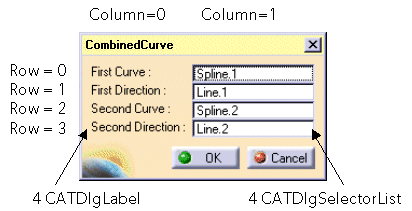 |
This figure shows the Combined Curve edition dialog box.
Two types of objects are used:
Rows and Columns are numbered starting from 0. |
Here is the code corresponding to the top row:
// Creates the CATDlgLabel for the input field's names.

_label_curve1 = new CATDlgLabel( this , CATString("labelc1") );
CATUnicodeString Promptc1 = "First Curve :";
_label_curve1 ->SetTitle(Promptc1);
...
// Creates the four input fields.
CATUnicodeString Prompt_nosel = "no selection";
_sel_curve1 = new CATDlgSelectorList(this,
                                     CATString("selc1"),
                                     CATDlgDataModify);
_sel_curve1->SetVisibleTextHeight(1);
_sel_curve1->SetLine(Prompt_nosel,0,CATDlgDataModify);
...
// first column: labels.
cst.Column=0;
cst.Row=0; _label_curve1 -> SetGridConstraints(cst);
// second column: input fields.
cst.Column=1;
cst.Row=0; _sel_curve1 -> SetGridConstraints(cst);
...
|
[Top]
This use case has demonstrated how to manage Combined Curve interactive.
It first shows how to implement the CATIEdit interface to activate Combined Curve edition.
Then, it creates a Combined Curve edition state dialog command, whose main points are to:
Insert method of the CATMmrLinearBodyServices
class if the combined curve is into an ordered set.Finally, this use case briefly presents a basic Combined Curve edition dialog box.
[Top]
| Version: 1 [Mar 2000] | Document created |
| Version: 2 [Oct 2003] | Document Updated- Ordered Geometrical Set integration |
| Version: 3 [Jan 2005] | CATImplementBOA usage instead TIE_CATIEdit |
| [Top] | |
Copyright © 2000, Dassault Systèmes. All rights reserved.