Mechanical Modeler |
The Contents of the Specification Container - Geometrical Features SetsWhat is an Ordered Geometrical Set, a Geometrical Set, a Body? |
|
| Technical Article | ||
AbstractThe article entitled "The Structure of a Part Document" [1] shows that the Part document contains four main containers, one of which is the specification container. This container contains the mechanical features. The mechanical features can be divided in three categories:
This article is the second one of a trilogy. Its aim is to detail the second category: what are the geometrical features sets, how are they created, how are they retrieved in a Part document. The first article [2] details the Part feature: what is the Part feature, how is it created, how is it retrieved in a Part document ?. Finally, the last article [3] details the geometrical features: what are they, their type, the existing geometrical features ,and how they are aggregated by the geometrical features sets. All of these articles are included in a set of documents presented in the "Mechanical Modeler Overview" article. [4]. |
The geometrical features set are mechanical features including geometrical features [3], and which can include another geometrical features sets. There are two kinds of geometrical features sets:
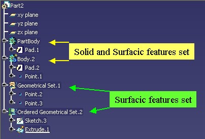
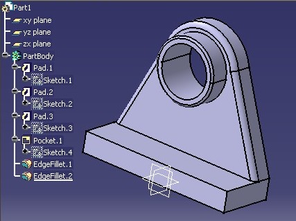
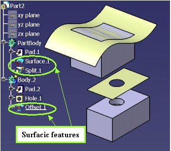
The following picture [Fig.1] shows them in the specification tree with their external name (English name) .
|
PartBody and Body.2 are solid
and surfacic features sets. They can contain both solid and surfacic
features.Geometrical Set.1 (GS) and Ordered Geometrical Set.2
(OGS) are surfacic
features sets. They can only contain surfacic features.The geometrical features sets are features created from StartUps [5] deriving from the MechanicalRoot StartUp.
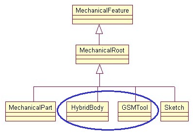 |
The next diagram, Fig.3, shows the interfaces which can help you to differentiate them.
 |
The CATIMmiGeometricalSet has been created to distinguish a surfacic features set from an surfacic and solid features set;
The CATIMmiOrderedGeometricalSet is implemented by the GSMTool StartUp, and characterizes the Ordered Geometrical Set features.
The CATIMmiNonOrderedGeometricalSet is implemented by the GSMTool StartUp, and characterizes the Geometrical Set features.
The Ordered Geometrical Set, and Body are geometrical features sets introducing two concepts:
This section is an overview on these two concepts, you are encouraged to read the referenced article [6] to find out more technical information.
The goal is having a set inside which features are ordered from the basic features (top) to features with huge historical graph (bottom). To reach it, a rule has been defined: "Each feature inside an ordered set can only have as input specifications features which are above it". It has been interactively implemented by following these behaviors:
Only features above the current feature are visualized in the 3D viewer.
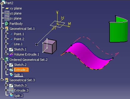
The goal is having a set inside which only the relevant features are taken into account. Let us consider the following sample:
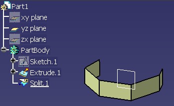 |
On the [Fig.4], just above, you can see in the 3D
viewer, even if Extrude.1 is not hidden (its icon is not
grayed), that only one surface is drawn. It is Split.1, the
surface coming from the split operation. Extrude.1 has been
like "absorbed" by Split.1. So feature such as Extrude.1
are named absorbed features, and those as Split.1 are
named absorbent features.
So the main particularities of an absorbed feature are:
The interface which defines the type of a feature, is CATIInputDescription.
In all Mechanical Modeler articles, the wording to designate both the Ordered Geometrical Set and the Body features, is "ordered set" .
The CATIGSMTool
interface, implemented both by the OGS and the Body feature [Fig.3], enables
you to know the status of a geometrical features set. The GetType method of
this interface answers 1 for an ordered set,
otherwise 0.
[Top]
The Body features occupy some volume in space, they can model objects of the real world and display attributes such as weight or center of gravity, once assigned a material specification.
 |
The term "solid and surfacic features set" is also used because a Body feature can contain surfaces features in addition to solid features. These surfacic features can be: points, wires, and surfaces but not volumes.
 |
The following table [Tab.1] shows that a Body feature can be only aggregated within a Part Feature [2], or an Ordered Geometrical Set.
| Part | GS | OGS | Body | |
| Body |
X |
X |
The method to create a Body feature is the CreatePRTTool
method of the CATIMechanicalRootFactoty interface. There are two signatures for this method.
CreatePRTTool method is the following:
...
  virtual CATISpecObject_var CreatePRTTool(const CATUnicodeString& iUserName,
                                           const CATISpecObject_var& iDestination) = 0 ;
...
|
iDestination = Part |
iDestination = OGS |
| The new set is located at the end of the Part | iDestination and the new Body have the same father. The new set is
located just after iDestination |
CreatePRTTool method is the following:
...
  virtual CATISpecObject_var CreatePRTTool(const CATUnicodeString& iUserName,
                                            const CATISpecObject_var& iDestination,
                                            int iPosition ) = 0 ;
...
|
iDestination = Part |
iDestination = OGS |
|
iPosition = 0 |
The new Body is located at the end of the Part | The new Body is located at the end of iDestination |
0 < iPosition <= size of iDestination |
The new Body is located at iPosition +1 within
Part |
The new set is located at iPosition +1 within iDestination |
The CreatePRTTool
methods check the validity of iDestination. If it is not the Part
feature, or an Ordered Geometrical Set, the returned value is NULL_var.
The main Body feature is the PartBody. It is automatically created at the Part document creation and cannot be deleted. The interface to retrieve it is CATIPartRequest (MecModInterfaces):
  ...
  CATIPartRequest *pICATIPartRequestOnPart =NULL ;
  HRESULT rc = spSpecObjectOnPart->QueryInterface(IID_CATIPartRequest,
                              (void**)&pICATIPartRequestOnPart );
  if ( SUCCEEDED(rc) )
  {
     CATBaseUnknown_var ThePartBody ;
     CATUnicodeString ViewContext="MfDefault3DView";
     rc = pICATIPartRequestOnPart->GetMainBody(ViewContext,ThePartBody);
  ...
|
Where spSpecObjectOnPart is a smart pointer on the Part. Refer to the "Retrieving
the Part feature" section of the referenced article [2]
to see the way to retrieve this smart
pointer.
About the view context: There is a default view context which is represented by the MfDefault3DView string. For some applications, such as Sheet Metal, another view context can be used to represent the same object in a different way. (MfUnfoldedView for an unfolded view). Except these two values, you can set anything, it will be the default 3D view, but it is not guarantee for future versions.
  ...
  CATIDescendants *pIDescendantsOnPart =NULL ;
  HRESULT rc = spSpecObjectOnPart->QueryInterface(IID_CATIDescendants,
                                           (void**)&pIDescendantsOnPart);
  if ( SUCCEEDED(rc) )
  {
     CATLISTV(CATISpecObject_var) ListResult ;
     rc = pIDescendantsOnPart ->GetAllChildren("CATIMechanicalTool",
                                                   ListResult);
  ...
|
The GetAllChildren method enables you to retrieve all the Body
features within the Part document. CATIMechanicalTool is a discriminant
interface for Body features see [Fig.3].
  ...
  CATIPartRequest *pIPartRequest =NULL ;
  HRESULT rc = spSpecObjectOnPart->QueryInterface(IID_CATIPartRequest,
                                                 (void**)&pIPartRequest );
  if ( SUCCEEDED(rc) )
  {
     CATLISTV(CATBaseUnknow_var) ListBodies;
     CATUnicodeString ViewContext ="MfDefault3DView" ;
     rc = pIPartRequest->GetSolidBodies(ViewContext,ListBodies);
  ...
|
ListBodies contains the list of all Body features for which
the CATIBodyRequest interface does not return E_FAIL. All
these Body features are aggregated by the Part feature. Notice that with CATIPartRequest,
you should specify the context.
Where spSpecObjectOnPart is a smart pointer on the Part. Refer to the "Retrieving
the Part feature" section of the referenced article [2]
to see the way to retrieve this smart
pointer.
The PartBody is the main body, those which holds the design of the part to create. In the case of a complex piece, it can be easier to decompose the design. So, a part of the design can be created in sub-bodies, in Body features, and next the final design will be realized in making operations between the Body features. These operations are boolean operations.
The boolean operations are: Assemble, Add, Remove, Intersect. Here is an example explaining the modifications which occur in a model due to a boolean operation.
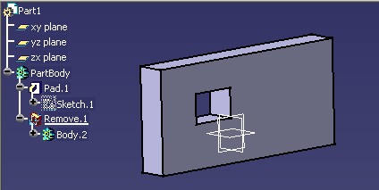 |
In the above picture, you can see that Body.2, previously
aggregated by Part1, has been operated
with the PartBody. In the PartBody feature, a new feature, Remove.1
has been created. Body.2 is now aggregated by Remove.1.
CATIPrtBooleanFactory (PartInterfaces) is the interface used to create
boolean operations. The CATIMechanicalTool (MecModInterfaces) and its GetBooleanOperation()
method enables knowing if the Body feature is a body used by a boolean
operation.
[Top]
The surfacic features set is mainly made of 0 thickness elements, such as planes, surfaces, wireframe geometry. But it can also contain volumes.
 |
The following table [Tab.2] summarizes where a surfacic features set can be aggregated. The first column is the feature to aggregate, and the first row specifies the aggregating feature.
| Part | GS | OGS | Body | |
| GS |
X |
X |
||
| OGS |
X |
X |
X |
Such as the Body feature, the methods to create an Ordered Geometrical Set,
or a Geometrical Set are methods of the CATIMechanicalRootFactory
interface. The CreateGeometricalSet method enables you to create a
Geometrical Set, and the CreateOrderedGeometricalSet enables you
to create an Ordered Geomerical Set. Both having the same behaviors, only the
first one has been used to explain their usage.
The signature of the CreateGeometricalSet method is the
following:
...
 virtual HRESULT CreateGeometricalSet(const CATUnicodeString& iUserName,
                                            const CATISpecObject_var& iDestination,
                                            CATISpecObject_var  & oGeomSet,
                                            int iPosition=-1 ) = 0 ;
...
|
The following array summarizes where is located the newly created set by taken the different parameters of the method into account.
iDestination = Part |
iDestination g Part |
|
iPosition = -1 |
The new set is located at the end of the Part | iDestination and the new set have the same father. The new set is
just after iDestination |
iPosition = 0 |
The new set is located at the end of the Part | The new set is located at the end of iDestination |
0 < iPosition <= size of iDestination |
The new set is located at iPosition +1 within
Part |
The new set is located at iPosition +1 within iDestination |
| Otherwise | E_FAIL | E_FAIL |
The CreateGeometricalSet and CreateOrderedGeometricalSet
methods check the validity of iDestination based on the previous
table [Tab.2]
There are two ways to retrieve a surfacic features set:
  ...
  CATIDescendants *pIDescendantsOnPart =NULL ;
  HRESULT rc = spSpecObjectOnPart->QueryInterface(IID_CATIDescendants,
                                           (void**)&pIDescendantsOnPart);
  if ( SUCCEEDED(rc) )
  {
     CATLISTV(CATISpecObject_var) ListResult ;
     rc = pIDescendantsOnPart ->GetDirectChildren("CATIMmiOrderedGeometricalSet",
                                                   ListResult);
  ...
|
In this example, you retrieve all the OGS directly under the Part feature, because the GetDirectChildren method is applied
on the MechanicalPart feature and CATIMmiOrderedGeometricalSet is
specific to the OGS [Fig.3]. With GetAllChildren on the same
feature, you retrieve all the OGS contained in the specification
container. To retrieve the OGS contained in another set, execute the GetDirectChildren method on
this set.
Using CATIMmiOrderedGeometricalSet you retrieve the OGS, using CATIMmiNonOrderedGeometricalSet you retrieve the GS, and with CATIMmiGeometricalSet you retrieve the surfacic features sets (OGS+GS).
  ...
  CATIPartRequest *pICATIPartRequestOnPart = NLLL ;
  HRESULT rc = spSpecObjectOnPart->QueryInterface(IID_CATIPartRequest,
                                       (void**)&pICATIPartRequestOnPart );
  if ( SUCCEEDED(rc) )
  {
     CATListValCATBaseUnknown_var ListSurfBodies ;
     CATUnicodeString ViewContext ="MfDefault3DView";
     rc = pICATIPartRequestOnPart->GetSurfBodies(ViewContext,ListSurfBodies);
  ...
|
ListBodies contains the list of all surfacic features sets for which
the CATIBodyRequest interface does not return E_FAIL: all
the Geometrical Set of the Part document, but only the Ordered Geometrical Set
features aggregated by the Part Feature [7].
Notice that with CATIPartRequest, you should specify the context.
Where spSpecObjectOnPart is a smart pointer on the Part. Refer to the "Retrieving
the Part feature" section of the referenced article [2]
to see the way to retrieve this smart
pointer.
A private surfacic features set is protected from interactive modifications. It means that end users cannot modify the structure of such a set:
Note, that however the private surfacic set is not protected from all CAA code modifications. CATIMechanicalRootFactory will not allow to define a private set as destination to aggregate a set. On the other hand, CATIDescendants interface will allow to append a set in a private set. So to aggregate a set in a set, to benefit from all necessary controls in terms of aggregation and privacy, the use of CATIMechanicalRootFactory is advised against CATIDescendants.
So generally speaking, if the end user wants to aggregate a feature, not necessarily a set, in a set, if he wants to use CATIDescendants he should first test if the set is private thanks to CATIGSMTool interface and its IsPrivate method. Note that a Body feature, implementing CATIGSMTool too, can be private.
[Top]
The specification container is one of the containers of the Part document. It groups together the mechanical features. Part of these are the geometrical features set. There are two types of geometrical features set:
The following table summarizes what they can contain (the first row is the aggregating feature):
| Part | GS | OGS | Body | |
| GS | X | X | ||
| OGS | X | X | X | |
| Body | X | X | ||
| Solid features | X | |||
| Point, Wire (including Sketch), Surface | X | X | X | |
| Volume | X | X |
This above table essentially shows:
The main interfaces are:
[Top]
| Version: 1 [Dec 2002] | Document created |
| Version: 2 [Nov 2003] | Ordered Geometrical Set Introduction + Open_Body renamed in Geometrical Set |
| Version: 3 [May 2004] | Document updated for R14 novelties |
| [Top] | |
Copyright © 2002, Dassault Systèmes. All rights reserved.