Mechanical Modeler |
The Contents of the Specification Container - The Part FeatureWhat is the Part feature? |
|
| Technical Article | ||
AbstractThe article entitled "The Structure of a Part Document" [1] shows that the Part document contains four main containers, one of which is the specification container. This container contains the mechanical features. The mechanical features can be divided in three categories:
This article is the first of a trilogy. The aim of this one is to detail the first category: what is the Part feature, how is it created, how is it retrieved in a Part document?. The second article [2] details the geometrical features sets: their type, how are they created, how are they retrieved in a Part document. At last, the third article [3] details the geometrical features: their type, the existing features and how they are aggregated by the geometrical features set. All of these articles are included in a set of documents presented in the "Mechanical Modeler Overview" article. [4]. |
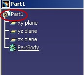
The Part feature is the highest feature in a Part document [Fig.1].
 |
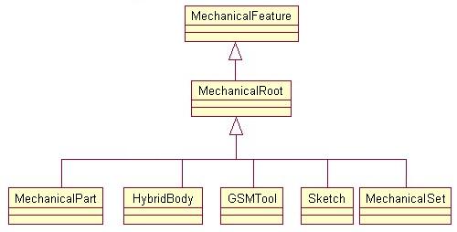
The Part feature is an instance of the MechanicalPart StartUp. The following diagram [Fig.2] shows this StartUp in the partial view of the mechanical StartUps [5] tree.
 |
At the top there is the MechanicalFeature StartUp. All the mechanical features derive from this StartUp. The MechanicalPart StartUp derives from the MechanicalRoot StartUp such as the HybridBody, the GSMTool, and the Sketch StartUps. The first two StartUps define the geometrical features sets described in the referenced article [2].
[Top]
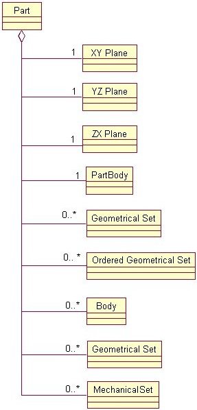
The Part feature contains the design of the object to be built. It aggregates (directly or indirectly) all the mechanical features of the Part document (except itself). The following UML schema [Fig.3] describes its contents.
 |
The Part feature aggregates:
The XY, YZ, YZ planes that together define an origin for the 3D space in which the Part is defined.
These are called the geometrical features sets. The PartBody (HybridBody) represents the main set. It is automatically created at the Part document creation and cannot be deleted. To enhance the clarity of the design or to facilitate its creation one can offset in other set sub-parts of the design. These other sets are Body features (HybridBody), Geometrical Set (GSMTool), and Ordered Geometrical Set (GSMTool) [2].
The Part feature is retrievable thanks to the CATIPrtContainer (MecModInterfaces) interface implemented on the specification container.
... CATISpecObject_var spSpecObjectOnPart = pIPrtCont->GetPart(); ... |
where pIPrtCont is the CATIPrtContainer interface pointer
on the specification container. Refer to the "Specification Container"
section in the "Structure of the Part Document" article [1]
to see how to retrieve this pointer.
Once you have a pointer on the Part, you can retrieve its reference planes using the CATIPrtPart interface (MecModInterfaces).
... CATIPrtPart * pIPrtPart = NULL ; spSpecObjectOnPart->QueryInterface(IID_CATIPrtPart,(void**) & pIPrtPart ) ; CATListValCATISpecObject_var ListRefPlanes = pIPrtPart ->GetReferencePlane(); ... |
ListRefPlanes contains three features which implement the CATIGSMPlane
(GSMInterfaces) interface.
The current feature is the current mechanical feature that you can interactively change with the "Define Object in Work" command. The available interface to retrieve or set the current feature is the CATIPrtPart interface.
[Top]
The specification container is one of the containers of the Part document. It groups together the mechanical features. One of these is the Part feature. It represents the end user design. It aggregates all the other mechanical features of the Part document.
[Top]
| Version: 1 [Dec 2002] | Document created |
| Version: 2 [Nov 2003] | Ordered Geometrical Set Introduction + Open_Body renamed in Geometrical Set |
| Version: 3 [May 2004] | Document updated for R14 novelties |
| Version: 4 [Mar 2007] | Document updated for R18 novelties - MechanicalSet and MechanicalElements |
| [Top] | |
Copyright © 2002, Dassault Systèmes. All rights reserved.