Mechanical Modeler |
Specification/Result Mechanism Applied to Mechanical FeaturesAn internal view of the mechanical features. |
|
| Technical Article | ||
AbstractThe aim of this article is to explain the Specification/Result modeler applied to the mechanical features. In other words, to describe the attributes of these features and explain the result produced by the Build/Update mechanism. This article is one among others in a series of articles which present various aspects of the Mechanical Modeler and which are introduced in the "Mechanical Modeler Overview" [1] article. |
The Feature Modeler [2] is a Specification/Result modeler in that it allows the creation of a network of inter-related data objects in order to be able to automatically update the "result" of an object whose "specification" has been modified. The Spec/Result Modeler provides an infrastructure for spec/result management, also called the Build/Update mechanism.
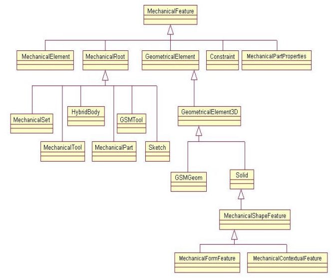
Mechanical features are features that derive from the MechanicalFeature StartUp. The UML schema below is an extract of the tree of StartUps deriving from the MechanicalFeature StartUp.
 |
"The Contents of the specification Container - Geometrical Features Sets" article [3] describes the geometrical feature sets (features deriving from the MechanicalRoot StartUp), and "The Contents of the specification Container - Geometrical Features" article [4] describes the geometrical features (those deriving from the GeometricalElement StartUp).
This article first consists in presenting the useful data (the modelization) needed to build, and to retrieve the result of the geometrical features. For these features, the result is a topological result, in other words a CATBody object [5]. First it is for the surfacic features, and then for the solid features.
This article next explains the internal modelization of the geometrical feature sets, in other words how each feature contained in a set takes part to the result of the set. First it is for the surfacic features set (feature deriving from the GSMTool StartUp), and then for the solid and surfacic features set (feature deriving from the HybridBody StartUp).
The last section of this article consists in to explain the usage of the CATIBodyRequest interface. It is the interface which returns the result of a geometrical feature sets.
[Top]
The surfacic feature is a feature that generally derives from either GeometricalElement3D or
from the GSMGeom [Fig.1] StartUps. It
is a feature for which the IsAsShape method of the CATIMf3DBehavior
interface always returns S_OK.
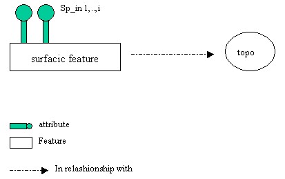
It has sp_in attributes but no sp_out attributes. The result of the build process, the topological result, is held by the surfacic feature itself. The following figure describes this:
 |
To retrieve the topological result, a CATBody
(NewTopologicalObject), you should use the GetBodyResult
method of the CATIGeometricalElement (MechanicalModeler) interface on
the surfacic feature.
[Top]
The solid feature is a feature which generally derives from either the MechanicalFormFeature or
from the MechanicalContextualFeature [Fig.1] StartUp. It
is a feature for which the IsAsSolid method of the CATIMf3DBehavior
interface always returns S_OK.
The solid feature has sp_in and sp_out attributes. Two of them are, therefore, particular; they are called ResultIN and ResultOUT though the real names of these two attributes are not significant. The CATIShapeFeatureBody (MechanicalModeler) interface enables you to retrieve these attributes. The ResultOUT attribute is valuated by a Solid feature which is aggregated by the solid feature. For Solid feature, with a uppercase, solid is the name of the StartUp, and for solid feature, with a lowercase, solid represents the nature of the feature. The following figure describes this:
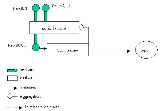 |
The Solid feature represents the result of the solid feature, meaning that
it holds the topological result produced by the Build method of the
CATIBuild interface [5]. In order to retrieve the
resulting CATBody of the solid feature, you have two means (*):
GetBodyOUT method of the CATIShapeFeatureBody
(MechanicalModeler) interface GetBodyResult
method of the CATIGeometricalElement interface on it. To obtain the
Solid feature, you should use the CATIShapeFeatureBody
interface and its GetResultOUT method. (*) In both these two cases, the CATBody is those of the default 3D view. You cannot retrieve the unfolded view for example.
The GetBodyResult method of the CATIGeometricalElement
interface enables you to retrieve a topological result, in other words a CATBody
object. The next diagram [Fig.4] represents the three cases
to take into account by applying this method on a solid feature:
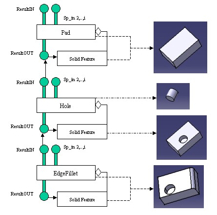 |
You can notice that:
GetBodyResult
method applied to the solid feature or to its Solid feature returns the same CATBody,
the one created by the Build method.GetBodyResult
method applied to the solid feature returns the topological result
representing the form of the feature (a cylinder). This CATBody
object is an internal data, created by the BuildShape method of
the CATIBuildShape interface, that you should not use. The topological result
created by the Build method on the solid feature, the Hole is returned by the GetBodyResult
method on its Solid feature. GetBodyResult
method applied to either the EdgeFillet or to its Solid feature returns the
topological result of the contextual feature. (the Pad with a hole and an
edge).[Top]
A surfacic features set is a set of features from zero to three dimension: points, wires, surfaces and volumes. The following picture Fig.5 shows some of them into Geometrical Set and Ordered Geometrical Set, the two kinds of surfacic features set.
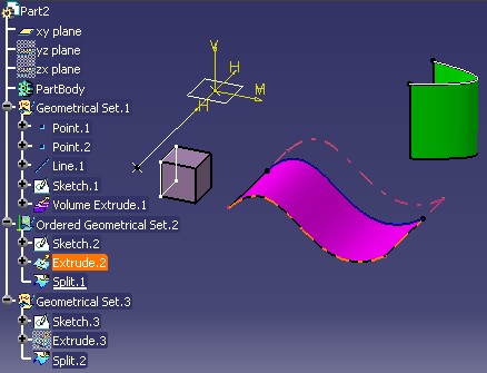 |
Just above the picture illustrates, or introduces three things:
Point.1, Point.2,
Line.1.Extrude.2, absorbed by Split.1
is not drawn in 3D, but it is possible to highlight it because its result
exists.
Ordered Geometrical Set.2 will be different of Geometrical Set.3
even they contain the same type of features. These three aspects are now detailed.
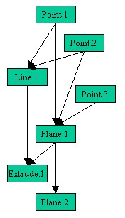
The features inside the surfacic features set form a net with their sp_in attributes. The next schema gives an example with two points and a line.
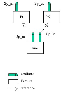 |
You can see that:
This schema, Fig.6, is independent of the type of the surfacic features set. The absorbed features are integrated into this net, and have also a result. You can use CATIGeometricalElement interface to retrieve their CATBody such as the other surfacic features.
The ordered surfacic features set has been introduced in R13 to strength the end user to create a feature which only relies on features above it in the specification tree [6]. Let us consider the consequences in term of graph thanks to the following two samples.
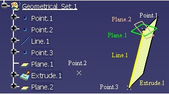
Above, Fig.7a, it is a Geometrical Set. After its creation, |
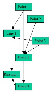 |
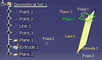
Now on Fig.7b it is an Ordered Geometrical Set with the same features as the
previous Geometrical Set. But the modifications done on the previous GS are not possible for
this OGS: |
 |
The previous samples are not really relevant, but you can imagine that for an huge graph the rule of order can be useful.
Attention, this order for an Ordered Geometrical Set is relative to the set itself. If inputs come from another sets, the design of the net can be no more ordered.
In order to retrieve the result of a surfacic features set, you must use the CATIBodyRequest
interface. Its usage is explained in the last section, the CATIBodyRequest Usage
section. The contents of the list returned by the unique GetResults method is
depending on the type of the surfacic features set:
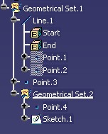
There are as many elements in the list as there are features aggregated by the
Geometrical Set feature, and implementing the CATI3DGeometricalElement interface (Sketches
are included). Just below, two
samples to illustrate the result of the GetResults method
applied on a
Geometrical Set feature.
 |
|
The GetResults method is not recursive for the Geometrical Set
features:
Point.4 and Sketch.1
are not in the list of Geometrical Set.1
Point.1
and Point.2 are not in the list of Geometrical Set.1
The GetResults method has the same result as the GetDirectChildren
method of the CATIDescendants interface with CATIGeometricalElement
(or CATI3DGeometricalElement) interface as filter.
Just below, two
samples to illustrate the result of the GetResults method
applied on an Ordered Geometrical Set (OGS).
 |
GetResults applied on Ordered Geometrical Set.1
returns:
GetResults applied on Ordered Geometrical Set.2
returns E_FAIL
|
In details, the behaviors of the GetResults method applied on an
OGS are:
Ordered Geometrical Set.2
returns E_FAIL.Extrude.1 does not appear in
the result of Ordered Geometrical Set.1. Ordered Geometrical
Set.2, Body.2 and Body.3 are added in the resulting
list of Ordered Geometrical Set.1Point.1
and Point.2 are added in the resulting list of Ordered Geometrical Set.1
However, even if the method is recursive, the GetResults method
it is not such as the GetAllChildren method of the CATIDescendants interface.
First the absorbed features are excluded, and then the result of a solid
and surfacic features set is completely different of the GetAllChildren
method, such as described in the next section.
[Top]
The solid and surfacic features set (SSS) can contain either solid and surfacic features excepted the volume [4]. The following picture is an illustration.
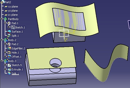 |
The above picture illustrates, or introduces, three things:
Surface.1 and Offset.1,
have their own result such as into a surfacic features set. They are included in the
list of features representing the result of the solid and surfacic features set.Extrude.1
is excluded of the Body.3's result.Body.2 there
is no CATBody for Pad.2, EdgeFillet.2 and
Hole.1, but rather only one CATBody,
the filleted and holed Pad. This CATBody is the form obtained after successive
operations named a chain. For the first two points you can refer you to the previous paragraph, the Surfacic Features Set Modelization paragraph. The next section explains the process used to create the result feature which is at the end of this "chain" of solid features.
The solid features inside a solid and surfacic features set are linked together by a kind of chain since the ResultIN attribute is valuated by the value of the ResultOUT attribute of the previous solid feature in the set. The next schema explains this chain with a solid and surfacic features set containing two solid features.
 |
(*) Not the last feature of the set such as former with the solid features set (MechanicalTool StartUp)., but the last solid feature. To be exact it is the last solid feature without update error.
This chain must be always consistent with the order of aggregation into the set. It is for this reason that to insert a solid feature in
a solid and surfacic features set you must use the CATIPrtProceduralView interface, and its InsertInProceduralView
method instead the CATIDescendants interface. The InsertInProceduralView
method:
The following set of interfaces are available in order to retrieve different information:
This interface is used to retrieve the first and the last solid feature of the chain. The last solid feature is that which aggregates the Solid feature holding the topological result.
This interface can be used to retrieve the previous or the next solid feature(s) from the current one.
The interface to retrieve the result of a solid and surfacic features set is the CATIBodyRequest interface too.
Just below, it is a sample to have an overview of the list returned by the GetResults
method.
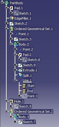 |
GetResults applied on PartBody returns:
GetResults applied on Body.2 and Body.3
returns E_FAIL
|
In details, the behaviors of the GetResults method applied on an
solid and surfacic features set (SSS) are:
E_FAIL. GetResults
is applied. But attention if the SSS is without solid features, the first
element of the list can be another kind of features than a Solid feature. Extrude.1 is not in the resulting list) Ordered Geometrical
Set.1, Ordered Geometrical Set.2, Body.2 and Body.3 are added in the resulting
list of PartBodyPoint.3
is added in the resulting list of PartBody.
[Top]
The CATIBodyRequest is the interface which retrieves the result of a geometrical features set. Here it is a piece of code which explains its usage.
...
CATIBodyRequest *pIBodyRequest= NULL;
pBody->QueryInterface(IID_CATIBodyRequest,(void**) &pIBodyRequest);
CATLISTV(CATBaseUnknown_var) ListResult ;
pIBodyRequest->GetResults("",ListResult);

CATIGeometricalElement * pIGeometricalElement = NULL ;
for (int i=1 ; i<= ListResult.Size(); i++)
{
   CATBaseUnknown_var spResult = ListResult[i];
   spResult->QueryInterface(IID_CATIGeometricalElement ,(void**) &pIGeometricalElement );

   CATBody_var spBodyResult = pIGeometricalElement->GetBodyResult();
}
...
|
where:
pBody is a pointer on a geometrical features set.
It can be:
otherwise the
method returns E_FAIL.
GetResults method is the context
for the result:
MfDefault3DView" to retrieve
the 3D resultunfolded" or "MfUnfoldedView" to retrieve the unfolded resultGetResults method is the list of
features which hold a topological result, and represent the result of the
geometrical features set.You can use the "Navigating a Part Document" use case [7] to analyze the result of the geometrical feature sets of your own Part documents.
[Top]
In this article you learned that:
GetBody method of the CATIGeometricalElement
interface applied on a surfacic feature, or on the Solid feature returns the CATBody result. The interface to retrieve the result of a geometrical features set is CATIBodyRequest.
The following array presents the contents of the list returned by the GetResults
method (column 2) depending on the type of the geometrical features set (the bolded
element of column 1), and its contents (the shifted elements of column 1).
| Set and its contents |
CATIBodyRequest::GetResults |
| Body | Solid feature + surfacic features (- absorbed) |
| OGS | surfacic features (- absorbed) |
| GS | All surfacic features |
| OGS1 OGS2 |
surfacic features (- absorbed) of OGS1 + surfacic features (- absorbed) of OGS2 |
| GS1 GS2 |
All surfacic elements of GS1 |
| Body
OGS |
Solid feature of Body + surfacic features (- absorbed) of Body + surfacic features (- absorbed) of OGS |
| OGS
Body |
Solid feature of Body +
surfacic features (- absorbed) of OGS + surfacic features (- absorbed) of Body |
| Body1
OGS Body2 |
Solid feature of Body1 + Solid feature of Body2
surfacic features (- absorbed) of Body1 + surfacic features (- absorbed) of Body2 + surfacic features (- absorbed) of OGS |
This array summarizes the most important things:
Attention, this table does not take into account the real order in the list.
[Top]
| Version: 1 [Mar 2004] | Document created |
| Version: 2 [Nov 2003] | Document updated for Ordered Geometrical Set |
| Version: 3 [May 2004] | Document updated for solid and surfacic features set |
| [Top] | |
Copyright © 2002, Dassault Systèmes. All rights reserved.