PPR Hub |
Product Modeler |
Integrating New Features in a Product StructureImplementing basic V5 behaviors for new applicative features |
| Use Case | ||
| CAAPstIntegrateNewFeatures > CAAPstINFBuildCatalog > CAAPstINFCreateDocument > CAAPstINFInitCont > CAAPstINFNavigate > CAAPstINFVisu > CAAPstINFGraphicalProperties > CAAPstINFEdit > CAAPstINFCCP > CAAPstINFDelete > CAAPstINFUpdate | ||
AbstractThis article discusses the CAAPstIntegrateNewFeatures use case. This use case explains how to create new features in an applicative container of a Product document and how to enable these features to be integrated in basic V5 mechanisms such as navigation, visualization, editing, update or CCP/Delete operations. |
This use case is intended to illustrate how to create new features in an applicative container of a Product document and how to integrate these features in the following basic V5 mechanisms:
This list is still incomplete and is planned to be enriched with illustrations of other mechanisms.
A new applicative feature can be created in a Product document without any behaviors at all. Basic behaviors can then be added little by little, one by one, without any interference of one with the other. The outline of this article follows this principle, as it is based on independent articles, each describing a basic mechanism, which, when put together, illustrate the coherent integration of new features in V5.
Some of the behaviors illustrated here are defined in various V5 Frameworks:
|
Framework |
Behavior |
|
ObjectModelerBase |
Cut, copy, paste, delete and specs tree navigation |
| ObjectSpecsModeler | Update |
| Visualization | Geometrical visualization |
| ApplicationFrame | Edit |
| Dialog | Edit dialog box |
| ProductStructure | Providers |
A quick note about Providers: The Provider mechanism, used to integrate "from scratch" features in a product structure, is implemented in the ObjectSpecsModeler framework. However, it is essentially used by ProductStructure implementations on Product features which is why this use case is based on a Product document example and delivered with ProductStructure framework CAA documentation.
A general pre-requisite knowledge of the frameworks described above may be required to fully understand this sample, but some links with other CAA V5 use cases will be indicated to help you navigate among them. To begin with, you may want to review the basics of the Feature Modeler that you can find in the "Feature Modeler Overview" technical article [1]. You may also find it useful to look over the "Product Structure Model" technical article [2] as well.
[Top]
The CAAPstIntegrateNewFeatures is a use case of the CAAProductStructure.edu framework that illustrates the integration of ObjectSpecsModeler, ObjectModelerBase, Visualization, ApplicationFrame, Dialog and ProductStructure framework capabilities in the scope of a Product document.
[Top]
This use case illustrates creating new applicative features "from scratch", instantiating them in an applicative container of a Product document and attributing different behaviors to them in order to be able to perform basic operations.
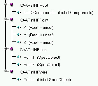
Here is an image of the feature catalog containing the "StartUps" which define the basic data structure of each of the features that will be created in this use case:
Fig 1: Contents of the CAAPstINFCatalog.CATfct file |
As you remember, the difference between an aggregated object and a referenced object in the context of the feature modeler is that:
Now that we understand what data objects we are working with and how they interact with each other, let's take a look at the Product document that we want to create. Initially, the Product document will be created in batch mode. A new applicative container of type "CAAPstINFCont" is created in which two "CAAPstINFRoot" features are instantiated, the first that will aggregate the other features and the second that will be used during the interactive scenario to demonstrate CCP capabilities. Next, five "CAAPstINFPoint" features are instantiated, each having different coordinate values. Then, a "CAAPstINFLine" feature is instantiated, whose attribute values reference the first two "CAAPstINFPoint" features. Finally, a "CAAPstINFWire" feature is instantiated and its attribute points to a list containing references to the last three "CAAPstINFPoint" features. The "CAAPstINFPoint", "CAAPstINFLine" and "CAAPstINFWire" features are then aggregated by the first "CAAPstINFRoot" feature. Here are the contents of the new Product document:
Fig. 2: Contents of the CAAPstINFDocument.CATProduct document.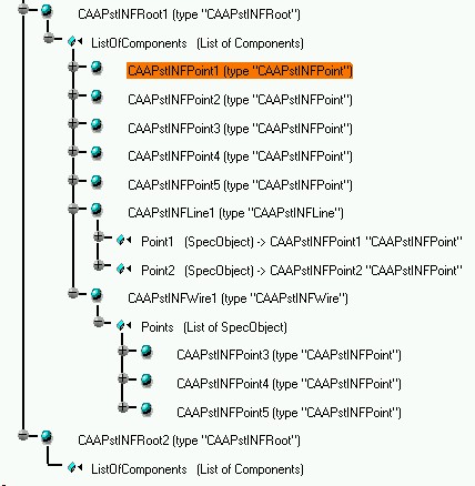 |
As you can see, the five "CAAPstINFPoint" features, the "CAAPstINFLine" feature and "CAAPstINFWire" feature are the elements in the list of components of the "CAAPstINFRoot1" feature. Also, notice that the "CAAPstINFLine1" feature points to "CAAPstINFPoint1" and "CAAPstINFPoint2" through a "SpecObject" link and that the "CAAPstINFWire1" feature points to "CAAPstINFPoint3", "CAAPstINFPoint4", and "CAAPstINFPoint5" through a "SpecObject" link as well.
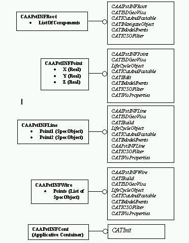
You can see, in this case, that "CAAPstINFRoot1" aggregates the other features, meaning that if "CAAPstINFRoot1" were to be deleted, all of the aggregated features would be deleted as well. The "CAAPstINFLine" and the "CAAPstINFWire" objects, on the other hand, only reference the points that make up their definitions, meaning that if they were to be deleted, the points would continue to exist independently. Inversely, however, in the case of the line, for example, if ever one of the points were to be deleted, it would be necessary to delete the line as well, since its definition would no longer be valid. Here is a UML diagram describing the links between these features:
Fig. 3: UML diagram of the three new features.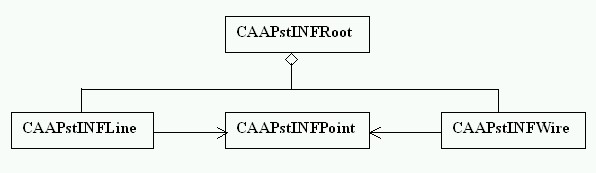 |
Note that nowhere in this document have we specified where the
"CAAPstINFRoot" nodes themselves are to be structured. This operation
will take place during the initialization of the applicative container, at
runtime. When the Product document is opened in the V5 interactive session, the
implementation of the CATInit::Init method for the
"CAAPstINFCont" applicative container is executed. This method
declares the provider implementations that will need to be executed during the
navigation and visualization processes in order to structure the
"CAAPstINFRoot" features under the Product root in the specs tree and
to be able to visualize the geometry of the point, line and wire features. So,
when the document is finally visualized, it looks like this:
 |
As you can see, the "CAAPstINFRoot1" and "CAAPstINFRoot2" features are structured directly under the Product root. This is defined in the navigation provider implementation. Remember that the navigation provider mechanism has been implemented for all products in a Product document. This means that during the navigation process, for each product node, any navigation provider that is currently declared to the document will be executed. So, in order to structure the "CAAPstINFRoot" features under the product root, the navigation provider code retrieves the "CAAPstINFRoot" types of features from the "CAAPstINFCont" applicative container and returns them as children nodes whenever the provider is called by the Product root object during the navigation process.
Note also that the geometry of the points and line is also visualized, whereas these are applicative features stored in an aplicative container and are not automatically taken into account during the visualization process. In order these objects to be treated, a visualization provider must also have been declared, which, when called, returns the list of the aggregating feature root nodes. Then, the CATI3DGeoVisu implementation for each feature root as well as for each aggreagted object in order to define the visualization.
See the technical article entitled "Using the Provider Mechanism" [3] for another example of how providers work.
Now, once the features are correctly represented in the navigation and visualization processes of the Product document, we would like to enable the features to be edited: a double-click on the feature node or geometrical representation causes the display of a dialog box, as seen in the following screen image:
Fig. 5: Editing a "CAAPstINFPoint" feature.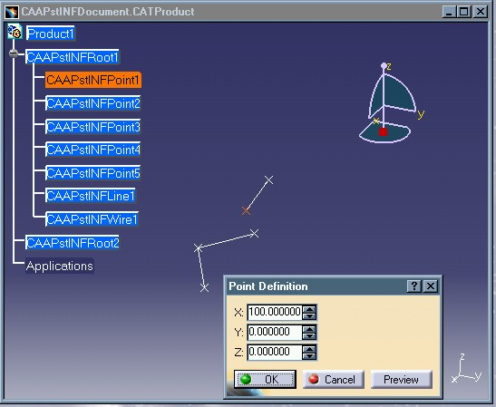 |
The dialog box entitled "Point Definition" contains the values of the coordinates of the selected point. Initially, these values were all set to 0.0. The Y coordinate value is changed to 100.0 in the dialog box and when selecting the OK button, the following modification occurs:
Fig. 6: Result of "CAAPstINFPoint" feature modification.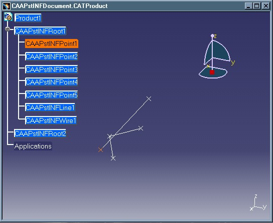 |
As you can see, the position of the point has changed and the impacted line has been re-drawn to reflect the referenced point's modification. This use case will show you in detail how this modification must be programmed.
Next, we want to illustrate copying a feature from one node to another or within the same node. This is done using the CCP mechanism. Here is a screen image showing this behavior:
Fig. 7: Copying a feature.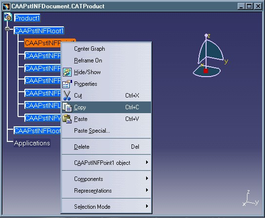 |
The contextual menu on the feature has been enabled to offer the Cut, Copy, Paste and Delete options. Here, the Copy operation has been selected. Next, a Paste operation will be selected on the second "CAAPstINFRoot" node, as seen below:
Fig. 8: Pasting a feature.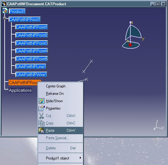 |
The "CAAPstINFPoint1" feature has been copied to create a new instance called " CAAPstINFPoint1.1" that is aggregated under "CAAPstINFRoot2". Here is the result of the CCP operation:
Fig. 9: Result of Copy/Paste operation.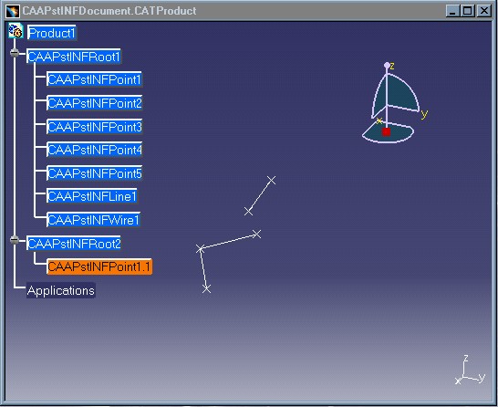 |
Lastly, we want to illustrate deleting a feature. To do this, we select the Delete option of the contextual menu on the "CAAPstINFPoint1" feature:
Fig. 10: Deleting a feature.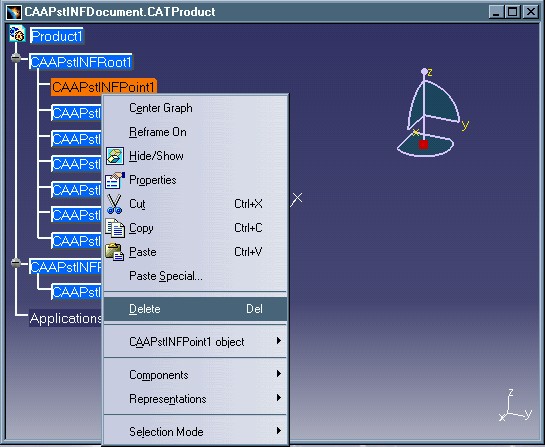 |
When the feature is deleted, any object pointing to it that is dependent on it for its definition, such as the "CAAPstINFLine1" feature, must be deleted as well. The result of the Delete operation on the point can be seen in the following screen image:
Fig. 11: Result of deleting a feature.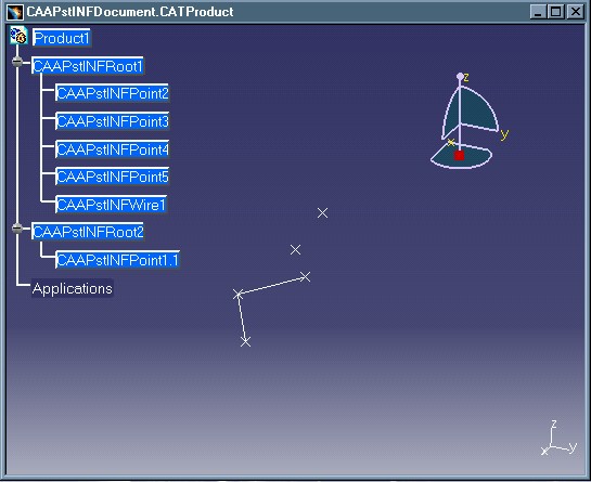 |
Note that two points are left: "CAAPstINFPoint2" which existed originally and "CAAPstINFPoint1.1" which is a copy of the "CAAPstINFPoint1" feature that was just deleted.
Below is a figure showing the interface implementations necessary for each new feature type created in order to enable the operations described above:
Fig. 12: Basic interface implementations necessary to integrate new features in a Product document.
 |
CATICutAndPastable - this interface is implemented by all four features: "CAAPstINFRoot", "CAAPstINFPoint", "CAAPstINFLine" and "CAAPstINFWire". It manages the cut and copy operations for the point, line and wire features and paste operation for the root feature.
CATINavigateObject - this interface is implemented only by the "CAAPstINFRoot" feature. It returns the list of its children, i.e., the features aggregated to it, so that they can be included in the specs tree.
CATICSOFilter - this interface is implemented by all four features, "CAAPstINFRoot", "CAAPstINFPoint", "CAAPstINFLine" and "CAAPstINFWire". It filters the CCP/Delete options of the contextual menu that are allowed on each particular feature. For example, for the "CAAPstINFRoot", we do not want to allow cut, copy or delete, but only paste. On the contrary, for the "CAAPstINFPoint", "CAAPstINFLine" and "CAAPstINFWire" features, we want to allow cut, copy and delete, but not paste. Depending on this implementation, the contextual menu options will be enabled or disabled.
CATI3DGeoVisu - this interface is implemented by all four features: "CAAPstINFRoot", "CAAPstINFPoint", "CAAPstINFLine" and "CAAPstINFWire". This interface defines the root features and creates the visualization of the geometric elements.
LifeCycleObject - this interface is implemented by the "CAAPstINFPoint", "CAAPstINFLine" and "CAAPstINFWire" features in order to handle the delete operation for these features.
CATIEdit - this interface is implemented only by the "CAAPstINFPoint". It allows the edition of the point feature by displaying a dialog box in which the point's coordinate values can be modified. (The edition of the line or wire features is not demonstrated here in order to keep this use case manageable in size.)
CATIModelEvents - this interface is implemented by all four features: "CAAPstINFRoot", "CAAPstINFPoint", "CAAPstINFLine" and "CAAPstINFWire".It allows each of these features to be connected to its root as well as enabling the refresh of their visualization in case they have been modified or deleted.
CATIBuild - this interface is implemented only by the "CAAPstINFLine" and "CAAPstINFWire" features. It allows the refresh of their visualization taking into account the changes that may have been made to any one of the referenced points that define them. This implementation is called automatically during the update process.
[Top]
The documentation of the CAAPstINFIntegrateNewFeatures use case contains the following articles:
[Top]
To launch the CAAPstIntegrateNewFeatures use case, you will need to set up the build time environment, then compile the following modules:
along with their prerequisites [4]. Several steps must be followed in order to completely execute the use case:
mkrun -c "CAAPstINFBuildCatalog CatalogStorageName"where
CatalogStorageName is the entire pathname, name and .CATfct
suffix of the catalog to be created. It is recommended that the new catalog be
stored in the CNext + resources + graphic directory of the current framework;
then, by updating the runtime view, the catalog will be moved to the runtime
directory and will be accessible by subsequent programs. This batch program
creates new StartUps in a new catalog. A catalog called
"CAAPstINFCatalog.CATfct" has also, however, been supplied with this
use case, so you can skip this step if you want to use it instead. If you do
re-create a new catalog by launching this batch program, be sure that the name
of the catalog is unique in the directory you specify, otherwise, your new
catalog will not be able to be saved.
mkrun -c "CAAPstINFCreateDocument CatalogName DocumentStorageName"where
CatalogName is the name and .CATfct suffix of
the catalog containing the StartUps to be retrieved in the document and DocumentStorageName
is the entire pathname, name and .CATProduct suffix of the
document to be created. This batch program will create the Product document
containing an applicative container in which the new features will be
instantiated. Like the catalog, a document called
"CAAPstINFDocument.CATProduct" has already been supplied with this
use case, so this step can be skipped as well.
Launch CATIA. When the application is ready, follow the scenario described below:
Select File + Open and select the CAAPstINFDocument.CATProduct
in the CAAProductStructure.edu/CNext/resources/graphic
directory or select the document you created yourself by executing the
batch program described in the previous step.
Collapse the "CAAPstINFRoot1" node by selecting the "+" symbol: notice that this root aggregates seven features of which five are of type "CAAPstINFPoint", one "CAAPstINFLine" and one "CAAPstINFWire".
Double-click on the "CAAPstINFPoint1" feature: the "Point Definition" dialog box appears.
Modify the values of any of the point coordinates and select OK or press Enter. Notice that the "CAAPstINFPoint1" feature has changed position and that the "CAAPstINFLine1" feature has also been updated.
Double-click on the "CAAPstINFPoint3" feature: the "Point Definition" dialog box appears.
Modify the values of any of the point coordinates and select OK or press Enter. Notice that the "CAAPstINFPoint3" feature has changed position and that the "CAAPstINFWire1" feature has also been updated.
Display the contextual menu on the "CAAPstINFPoint1" feature.
Select "Copy".
Display the contextual menu on the "CAAPstINFRoot2" feature.
Select "Paste". Notice that a new feature, "CAAPstINFPoint1.1" has been aggregated to the "CAAPstINFRoot2" feature by copy/paste. The new point has the same coordinate values as the point it is copied from, so its geometry cannot be visualized.
Double-click on the "CAAPstINFPoint1.1" feature: the "Point Definition" dialog box appears.
Modify the values of any of the point coordinates and select OK or press Enter. Now you can visualize the "CAAPstINFPoint1.1" since its coordinates are no longer the same as those of "CAAPstINFPoint1". The "CAAPstINFLine1" feature has not changed at all because it is not dependent on the copy of "CAAPstINFPoint1" but on "CAAPstINFPoint1" itself.
Display the contextual menu on the "CAAPstINFPoint1" feature again.
Select "Delete". Notice that the "CAAPstINFPoint1" feature has been deleted and that the "CAAPstINFLine1" feature has also been deleted because it can no longer exist without one of its reference points. The initial copy of "CAAPstINFPoint1", however, continues to exist.
[Top]
The CAAPstIntegrateNewFeatures use case is made of several modules of the CAAProductStructure.edu framework:
| Windows | InstallRootDirectory\CAAProductStructure.edu\CAAPstINFBuildCatalog.m
and CAAPstINFCreateDocument.m and CAAPstINFInterfaces.m and
CAAPstINFCommands.m and CAAPstINFModeler.m |
| Unix | InstallRootDirectory/CAAProductStructure.edu/CAAPstINFBuildCatalog.m
and CAAPstINFCreateDocument.m and CAAPstINFInterfaces.m and
CAAPstINFCommands.m and CAAPstINFModeler.m |
where InstallRootDirectory is the directory where the CAA CD-ROM
is installed.
These modules are:
[Top]
You can now successively get to:
[Top]
The CAAPstIntegratingNewFeatures use case has shown you how to create new features "from scratch" and how to integrate them in a product structure and enable them to have certain basic V5 behavioral capabilities.
[Top]
| [1] | Feature Modeler Overview |
| [2] | The Product Structure Model |
| [3] | Using the Provider Mechanism |
| [4] | Building and Launching a CAA V5 Use Case |
| [Top] | |
| Version: 1 [May 2002] | Document created |
| [Top] | |
Copyright © 2002, Dassault Systèmes. All rights reserved.