The information in this section will help you create and manage the drilling
(or axial machining) operations in your manufacturing program. The following
topics are dealt with:
Approach clearance (A)
Defines a safety distance along the tool axis for approaching
the hole reference.
The manufacturing attribute is MFG_CLEAR_TIP. |
Approach clearance 2 (A2)
Only for Boring and Chamfering, Chamfering Two Sides,
and Back Boring operations, this parameter defines a safety
distance along the tool axis for approaching the chamfering
or back boring pass.
The manufacturing attribute is MFG_CLEAR_TIP_2. |
Breakthrough (B)
Defines the distance in the tool axis direction that the tool
goes completely through the part.
The manufacturing attribute is MFG_BREAKTHROUGH. |
Plunge mode
Allows
you to specify an axial plunge from the hole reference at plunge
feedrate prior to machining.
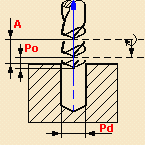
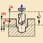
The overall plunge distance is determined as follows:
Approach clearance + (Plunge depth - Plunge
offset)
where Plunge depth is determined by a tool tip or tool diameter
value.
The manufacturing attribute is MFG_PLUNGE_MODE.
|
Plunge offset (Po)
Specifies
the plunge offset value.
The manufacturing attribute is MFG_PLUNGE_OFFST. |
Plunge diameter (Pd)
Specifies the plunge diameter value.
The manufacturing attribute is MFG_PLUNGE_DIAMETER. |
Plunge tip (Pt)
Specifies
the plunge tip distance.
The manufacturing attribute is MFG_PLUNGE_TIP. |
Plunge for chamfering
For a Boring and Chamfering operation, if a Plunge
mode is selected (By Tip or By Diameter), you can deactivate
the plunge motion for the Chamfering phase of the operation
by deselecting the Plunge for chamfering checkbox.
In this case, the plunge motion will be done for the boring
phase only. |
Depth mode
Defines
how the depth computation is to be done.
Depending on the type of operation this can be done as a function
of the tool tip, shoulder, diameter or a distance value. The
manufacturing attribute is MFG_DEPTH_MODE. |
Dwell mode
Defines
the dwell by means of a number of revolutions or time duration.
- Revolutions: Specifies the number of revolutions
for the dwell
- Time: Specifies the time duration of the
dwell.
|
Shift mode
Specifies the
shift mode used to offset the tool just before retracting.
- By linear coordinates
Shift along X: Specifies the shift along X
Shift along Y: Specifies the shift along Y
Shift along Z: Specifies the shift along Z
- By polar coordinates
Shift distance: Specifies the shift distance
Shift angle: Specifies the shift angle
The values entered for the selected shift mode determine
the angle at which the active part of the boring bar stops and
the amount of the tool displacement.
For a shift defined by polar coordinates
(90deg, 1.5mm), the tool is displaced 1.5mm as indicated by
the arrow in the figure below.
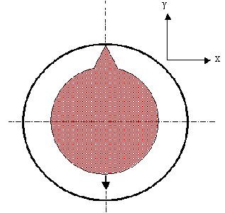
The same shift motion could be obtained by the
linear coordinates (0mm, 1.5mm, 0mm).
|
Max depth of cut (Dc)
Defines the maximum depth of cut for:
- each peck in a Drilling Deephole operation
- each break chips pass in a Drilling Break Chips operation.
The manufacturing attribute is MFG_AXIAL_DEPTH.
|
Retract
Defines the retract clearance after the machining pass in a
Back Boring operation.The manufacturing attribute
is MFG_RETRACT_CLEAR_TIP.
|
Retract offset (Or)
Defines
the value of:
- the back motion used to break chips after each drilling
pass in a Drilling Break Chips operation
- the offset where machining feedrate starts before each
new peck in a Drilling Deephole operation.
The manufacturing attribute is MFG_OFFSET_RET.
|
Decrement rate
In
a Drilling Deephole operation, this parameter decreases
the effective depth of cut at each new peck until the total
depth is reached. Depth of peck 1 = Max depth of cut (Dc)
Depth of peck 2 = Dc * (1-Decrement rate)
Depth of peck 3 = Dc * (1-2*Decrement rate)
and so on.
If Decrement rate is equal to zero, the Maximum depth of
cut is applied at each new peck as a constant step.
The manufacturing attribute is MFG_DEPTH_DEC.
Decrement limit
Coefficient used to determine the maximum allowed depth of cut
for a peck in a Drilling Deephole operation.
The depth of a new peck never becomes smaller than the Maximum
depth of cut multiplied by the Decrement limit.
That is:
Depth of current peck > Maximum depth of cut * Decrement limit.
When:
Depth of current peck = Maximum depth of cut * Decrement limit
this depth is kept for all remaining pecks until the total depth
is reached.
The value of Decrement limit must be greater than zero.
The manufacturing attribute is MFG_DEPTH_LIM.
Example of
Decrement rate and Decrement limit:
A Drilling Deephole operation uses the following parameters:
Maximum depth of cut = 10mm
Decrement rate = 0.1
Decrement limit = 0.8
Therefore, depth of current peck will always be greater than
8mm (that is, 10mm*0.8).
Depth of peck 1 = 10mm
Depth of peck 2 = 9mm
Depth of peck 3 = 8mm
Depth of remaining pecks = 8mm.
|
Automatic ROTABL
Allows the generation of rotation motions between drilling
points that have different tool axes. This capability works
with a 3-axis milling machine with rotary table when ROTABL/
output is requested.Rotary motions are displayed during Replay.
ROTABL/ instructions are generated in the output file.
Facilitates environment setup by minimizing the requirement
on post processors (avoids having to deal with X, Y, Z, I, J,
K outputs for rotary tables).
Provides the NC programmer with a more accurate tool path simulation
for machine tools with rotary table.
Note: No rotary motion is performed if a linking macro
motion is defined (and activated) on the drilling operation.
If activated, the linking macro is always performed between
the points to machine.
|
Output CYCLE syntax
Specifies how the NC output is to be generated: output in
CYCLE mode or in GOTO mode. If you
want to generate CYCLE statements, you must select the
Output CYCLE syntax checkbox in the Strategy tab page
and set the
Syntax Used option to Yes in the NC Output generation dialog
box.
Otherwise, GOTO statements will be generated.
Note that when several axis orientations are present in a
machining pattern, output of the components of the tool axis
orientation is possible whenever the NC data format is set to
Axis (X, Y, Z, I, J, K) in the Part Operation's Machine Editor.
|
First compensation
Specifies the first tool compensation number for the operation.
|
Second compensation
For Boring and Chamfering and Chamfering Two Sides operations,
this parameter specifies the second tool compensation number
for the operation. |
Compensation application
mode
Specifies how the corrector type specified on the tool (P1,
P2, P3, for example) is used to define the position of the tool:
Output point or Guiding point.
- Output point: the tool compensation point
is generated in the output file. The toolpath computation
is done according to the tool tip.
- Guiding point: the tool motion is computed
according to the tool compensation point and the tool compensation
point is generated in the output file.
Note that the tool compensation point is defined on the tool
and used on the operation.
The Compensation application mode defines the tool position
to reach.
Toolpath computation and Output Point
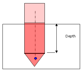
If Compensation Application Mode is set to Output point then
Depth mode option (Tip/Shoulder or Distance/Diameter) is taken
into account for tool path computation.
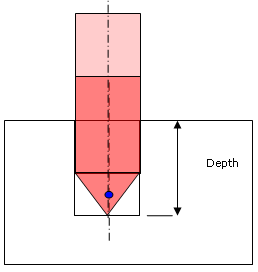
Examples:
P2 compensation is defined on the tool and used on the drilling
operation.
Compensation application mode = Output point.
 |
 |
|
Depth mode = Tip
|
Depth mode = Shoulder
|
|
The active compensation point (blue dot in figures
above) is only used as output point in the generated
file (APT source). |
Toolpath computation and Guiding Point
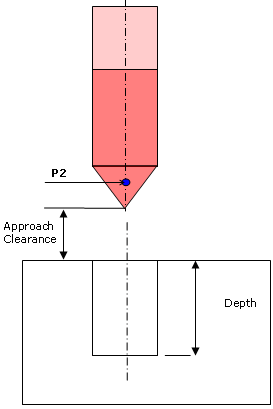
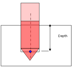
When Compensation application mode is set to Guiding point,
the tool compensation point selected on the operation is taken
into account to respect the depth to machined on the operation.
All the points to reach with the tool are computed with respect
to the activated compensation point. In this case Depth mode
(Tip/Shoulder or Distance/Diameter) is no longer taken into
account.
Only the tool compensation point is used to compute the different
tool positions to reach during the cycle.
Example:
P2 compensation is defined on the tool and used on the drilling
operation.
Compensation application mode = Guiding point.
 |
 |
|
The active compensation point is represented
by the blue dot in figures above. |
If Compensation application mode is set to Output point then
tool path computation is done without modification: Depth mode
option (Tip/Shoulder or Distance/Diameter) is applied, if it
exists on the operation.
Tool Path Output
- GOTO statements output:
The tool compensation point is always generated in the output
file.
There is no influence of the Output point or Guiding point
option.
- CYCLE statement output
Coordinates of points between CYCLE/ and CYCLE/OFF statements
are always the coordinates of the points to machine.
Output File Generation
Cycle parameters (%MFG_TOTAL_DEPTH, %MFG_TOTAL_DEPTH_COMP)
valuation depends on the Compensation application mode defined
on the operation.
%MFG_TOTAL_DEPTH and %MFG_TOTAL_DEPTH_COMP are computed parameters.
- MFG_TOTAL_DEPTH: Total depth machined by the operation.
This includes the hole depth, breakthrough, and tool tip
length.
- MFG_TOTAL_DEPTH_COMP: Total depth machined by the operation
up to the tool compensation point selected for the operation.
This includes hole depth, breakthrough and tool tip length
up to the compensation point.
Then the value depends on the tool compensation used on the
operation (if Compensation application mode is set to Guiding
point).
The parameter %MFG_COMPENSATION_MODE (1: output point / 2:
guiding point) can be defined on the NC instruction of the axial
machining operation.
|
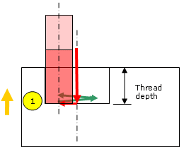
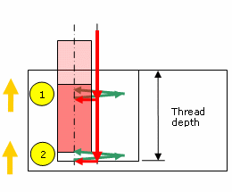
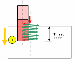
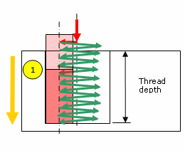
Machining direction
Specifies the direction of the tool motion.
- Top to bottom: tool motion is from
the top to the bottom of the thread. This involves
conventional cutting.
- Bottom to top: tool motion is from
the bottom to the top of the thread. This involves
climb cutting, and results in a better quality thread.
Machining strategy
Specifies how the tool path is to be computed.
- Mono-pass (default value)
Machining motion is done in one pass. Tool is considered
as a mono-cutting level tool.
- Optimized passes
This strategy is useful for thread mill tool (more
than one cutting level exists on the tool). It is
not available when a boring bar is used.
Toolpath depends on the tool characteristics and
thread depth.
One or more helical (height = pitch) toolpaths can
be generated: the number of helical toolpaths depends
on the effective thread length of the tool and the
thread depth of the hole.
Note about thread mills and effective thread length:
Length1 depends on Cutting length (Lc) and Taper
angle (Ach). See
Thread Mill for geometry parameters.
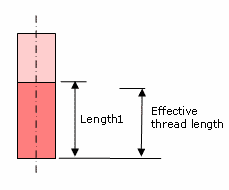
Cutting levels on the tool is the number of thread
pitches that can be machined during one helical motion.
The number of cutting levels is defined as follows:
Number of effective cutting levels = int (Length 1 /
tool pitch)
Effective thread length = number of cutting levels *
pitch.
Note that between helical toolpaths:
- approach macro motion is done before each helical motion
- retract macro motion is done after each helical motion.
The following figure illustrates the motion involved for
2 helical toolpaths.
|
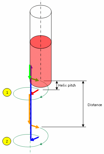 |
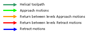
Key to colors and arrows in this figure:
|
|
Helical toolpath is done for one helix pitch height. Distance
is defined from start of one helix motion to next start of next
helix motion.
Distance = effective thread length of the tool + pitch.
|
|
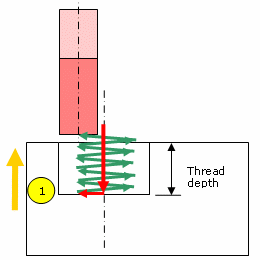
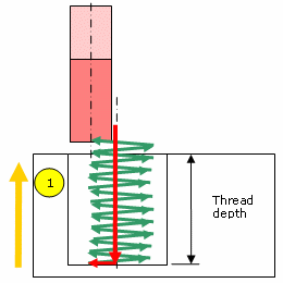
The figures below illustrate the various combinations depending
on tool type, tool's effective thread length, thread depth of
hole, machining strategy, machining direction. |
|
Thread mill, Machining strategy=Optimized passes, Machining
direction=Top to Bottom: |
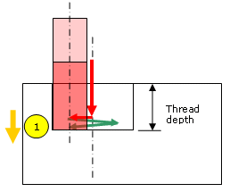 |
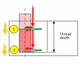 |
|
Thread mill, Machining strategy=Optimized passes, Machining
direction=Bottom to Top: |
 |
 |
|
Thread mill or Boring bar, Machining strategy=Mono-pass, machining
direction=Top to Bottom: |
 |
 |
|
Thread mill or Boring bar, Machining strategy=Mono-pass, Machining
direction=Bottom to Top: |
 |
 |
|
|
Machining mode
Specifies the machining mode: Standard or Helical. |
Distance between paths (Dp)
Defines the maximum distance between two consecutive tool paths
in a radial strategy .
|
Number of paths (Np)
Defines the number of tool paths in a radial strategy. |
Axial mode
Defines how the distance between two consecutive levels
is to be computed.
Maximum depth of cut (Mdc)
Defines the maximum depth of cut in an axial strategy.
Number of levels (Nl)
Defines the number of levels to be machined in an axial
strategy.
|
Sequencing mode
Specifies the order in which machining is to be done:
Axial: axial machining is done first then
radial
Radial: radial machining is done first then
axial.
|
Percentage overlap
Specifies the percentage overlap. |
Automatic draft angle
Specifies the draft angle to be applied on the circular
flank between the top and bottom of the hole. |
Helix mode
Defines
how the helix computation is to be done.
The manufacturing attribute is MFG_HELIX_MODE.
Pitch (P): Specifies the helix pitch
Angle (Ang): Specifies the helix angle.
|
|
|
Compensation output
Allows you to manage the generation of Cutter compensation
(CUTCOM) instructions in the NC data output:The following options
are proposed:
- If 2D Radial profile is selected, both the
tool tip and cutter profile will be visualized during tool
path replay. Cutter compensation instructions are automatically
generated in the NC data output. An approach macro must
be defined to allow the compensation to be applied.
- If 2D Radial tip is selected, the tool tip
will be visualized during tool path replay. Cutter compensation
instructions are automatically generated in the NC data
output. An approach macro must be defined to allow the compensation
to be applied.
- If None is selected, cutter compensation
instructions are not generated in the NC data output. In
this case, please refer to How
to generate CUTCOM syntaxes.
|
 Helical
Interpolation for Circular Milling and Thread Milling Helical
Interpolation for Circular Milling and Thread Milling
A helical interpolation instruction can be generated in the
output file (APT source or Clfile) for helical tool motions.
The machine specified on the Part Operation must support Helical
interpolation and the corresponding checkbox must be selected
in the
Machine Editor.
The Helical Interpolation option must be set to From machine
in the Generate NC Output dialog box. If this option is set
to None, then GOTO instructions are generated for
the helical motion. For more information, see
Generate APT Source or
Generate Clfile.
Axial Machining Geometry Considerations
Geometry parameters are managed in the Geometry tab page
 . .
Machining Patterns
A machining pattern comprises two sets of data:
- Pattern geometry: hole positions/axes, top element
- Pattern usage or technology data: Ordering mode,
Jump distance, local entry/exit distances, local depth,
activate/deactivate status.
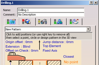
When you create a new axial machining operation, the
New Pattern command in the list prompts you to create
a machining pattern for the operation.
You can add positions to this new machining pattern by clicking
the sensitive text (No Point or x Points). This opens the Pattern
Selection dialog box that lists all available machining and
design patterns. Just select one of the existing patterns and/or
select geometry in the 3D view to define the hole positions.
The new machining pattern is created when you create the
machining operation. The pattern geometry and technology data
is stored and the new pattern is assigned an identifier
Machining Pattern.x.
If there are already machining patterns on previous operations,
the list allows a quick selection of an existing pattern. If
selected, the existing pattern is shared between the operations.
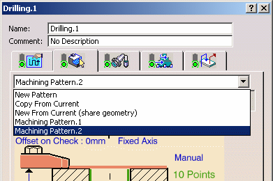
You can also use the following
commands in the list for assigning a machining pattern to the
operation.
Copy from Current: The machining pattern (geometry
and technology data) is duplicated. The pattern cannot be shared.
It is possible to modify the machining data in the current machining
operation without impacting other operations.
New from Current (share geometry): The machining
pattern (geometry and technology data) is duplicated. The pattern
can be shared. If the pattern is modified, all operations using
it will be impacted.
New Pattern: A new machining pattern is created
with the geometry and technology data that you specify.
Modification of a machining pattern is possible using the
Machining Pattern editor only. This editor can be opened by
double-clicking the machining pattern in the manufacturing view.
Please refer to
Machining Patterns for more information.
Note that it is possible to reference in a machining pattern
one or more 3D Wireframe features (that is, Projection, Symmetry,
Rotation and Translation operators) containing at least one
point.
Tool Axis Initialization from Pattern Selection
When you select pattern points by means of design holes or
circular edges, the orientation of tool axis is automatically
initialized using semantic information related to the selected
geometry.
If a geometrical point is selected there is no semantic information
to determine the tool axis. In this case, the tool axis is initialized
from the z-axis of the absolute axis system.
You can modify the tool axis by right-clicking a pattern
point and selecting Edit Local Axis (see
Contextual Menu on Pattern Points for more
information).
Pattern Ordering Modes
Holes that are selected for a machining pattern can be
ordered according to the following modes:
- Closest: to obtain the shortest possible
tool path
- Manual: to obtain a user-defined numbered
sequence
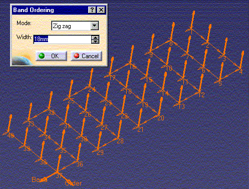
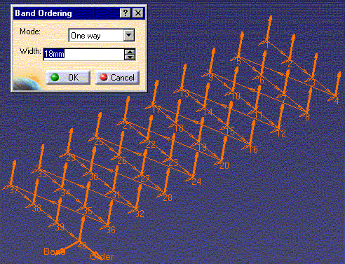
- By Band: to obtain a Zig Zag or One Way configuration
according to a set of bands that have a user-defined width.
- Zig Zag ordering of a pattern of 40 points
for a band width of 18mm is illustrated below:
- One Way ordering of the same points and
same band width is illustrated below:
- Reverse Ordering: Reverses the numbered sequence
of pattern points (for example, points numbered 1 thru 10
will become numbered 10 thru 1).
|
Managing Pattern Points
Contextual Menu on 'No Points / x Points'
Sensitive Text
A number of contextual commands are available for managing
hole positions when you right click the 'No Points / x Points'
sensitive text in the Geometry tab page.
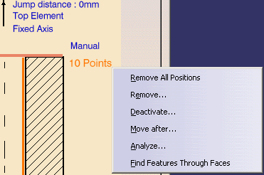
- Remove All Positions: Removes all positions
from the pattern.
- Remove: Displays a dialog box for removing
selected positions from the pattern.
- Deactivate: Displays a dialog box for deactivating
selected points of the pattern.

- Move After: Displays a dialog box for moving
one or more positions after a specified position in the
pattern. Only available when Pattern Ordering mode is set
to Manual.
- Analyze: Displays the Geometry Analyser for
consulting the status of the referenced geometry.
- Find Features Through Faces: Allows you to
quickly locate circular edges in a selected face. Please
refer to Select Hole Design Features
for Machining.
Contextual Menu on Pattern Points
A number of contextual commands are available when you right-click
a pattern point.
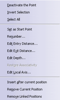
- Deactivate the Point: Deactivates the selected
point in the pattern. An O symbol indicates that the point
is omitted from the pattern. A deactivated point can be
activated in the pattern again.
- Invert Selection:
All omitted points are retained in the pattern again; pattern
points become omitted points.
- Select All: Allows you to include all omitted
points in the pattern again.
- Set as Start Point: Allows you to choose
the start point for the pattern.
- Renumber: Allows you to renumber points in
the pattern. Only available when Pattern Ordering mode is
set to Manual.
- Edit Entry Distance and Edit Exit Distance:
Allows you to locally edit Entry
and Exit distances at individual
points in a hole pattern. This can be useful for locally
specifying a clearance that is greater than the one defined
by the jump distance/approach clearance
discussed below.
- Edit Depth: Allows you to edit the depth
of a pattern point.
- Restore Associativity:
Restores the original
values taken from the selected design feature if these were
modified by the user, and so restore associativity with
the feature.
- Edit Local Axis: Allows you to locally modify
the tool axis at a point. The Tool Axis dialog box appears.
|
|
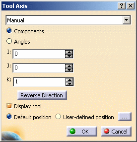
Choose one of the proposed
methods for defining tool axis orientation:
Manual. Choose one
of the following:
- Components to
define the tool axis orientation
by means of I, J and K components.
- Angles to define
the orientation by means of
a rotation specified by means
of one or two angles.
Selection. If you
select a line or linear edge, the
tool axis will have the same orientation
as that element. If you select a
planar element, the tool axis will
be normal to that element.
Points in the View.
Just select two points to define
the orientation.
Feature defined. Select
a machining feature in the 3D viewer.
For example, if you select an axial
machining feature then the axis
of the feature is taken as the tool
axis.
The tool axis is visualized by means
of an arrow. The direction can be reversed
by clicking Reverse Direction
in the dialog box. Just click OK to accept
the specified tool axis orientation.
You can also choose to display the tool
at the Default position or at
a User-defined position.
For a user-defined position, click the
[...] button and select the desired
position in the 3D viewer.
For more information about this dialog
box please refer to
Define the Tool Axis.
|
- Insert after Current Position: Allows you
to insert one or more positions (or patterns) after the
current point in the pattern. Only available when Pattern
Ordering mode is set to Manual.
- Remove Current Position: Deletes the current
point from the pattern.
- Remove Linked Positions: Deletes the current
point and all linked positions from the pattern. Linked
positions are points from the same design pattern, for example.
|
Inversing Pattern Ordering
An Inverse
pattern ordering checkbox is available in the Geometry
tab page to allow an operation to locally override the ordering
of the Machining Pattern by inversing it.
- If not selected, the Machining Pattern will be machined
as defined (and as shown in the 3D view).
- If selected, the tool path computation will begin at
the last point and finish at the first point.
This will not modify the ordering on the Machining Pattern:
the pattern numbers shown in the 3D View are not modified.
This option is useful in the following cases.
- When machining symmetrical parts. Please refer to
Opposite hand machining.
- To save machining time when managing two operations
sharing the same Machining Pattern on a large part. The
first operation can be set to machine from the first position
to the last one, and the second operation can be set machine
from the last position to the first one.
|
Overall Tool Axis Orientation
Right click the Tool axis strategy sensitive text
in the Geometry tab page and select one of the following options
to specify the general tool axis orientation:

Fixed Axis: the tool axis
orientation is the same for all the selected points
Variable Axis: the tool axis
orientation can vary from one point to another
Normal to PS Axis: the tool
axis orientation is determined by the normal to the selected
part surface.
Note that the tool axis orientation can be inverted
by clicking the tool axis symbol in the Geometry tab page.
|
Projection and Top Element Modes
In the Geometry tab page you can choose between Projection
and Top Element modes by clicking on the sensitive
text.
The following figure illustrates Projection mode.
The reference pattern points are projected onto the selected
part surface. The projected points and the axes normal to the
surface define the hole positions to be drilled.
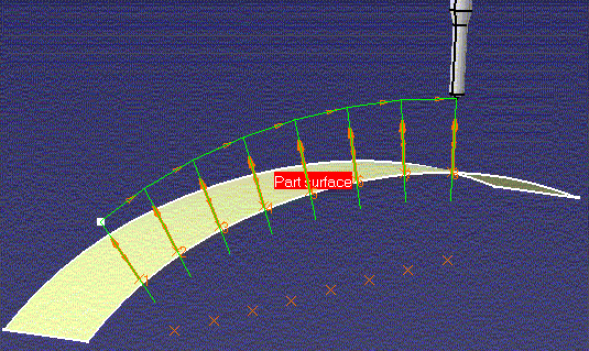
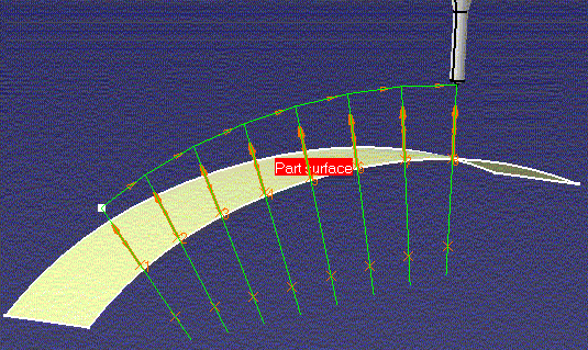
The following figure illustrates Top Element mode.
The reference pattern points define the hole positions to be
drilled. The machining depth takes into account the normal distance
between the reference points and the selected part surface.
|
Bottom Plane
If a bottom plane is selected,
the machining depth is the distance between the hole origin
and its projection on the bottom plane. This machining depth
is computed for each hole in the machining pattern.
The depth shown in the geometry panel is the machining depth
computed for the first hole. The Machine different depths
setting is ignored when a bottom plane is selected.
|
Origin Offset
You can specify an Origin
Offset in order to shift the entire tool path by the specified
amount.
|
Jump Distance
The jump distance allows an
extra clearance for moving in Rapid motion between the
holes to be drilled whenever this distance is greater than the
approach clearance.
For example, for an approach clearance of 2.5mm and a jump distance
of 10mm, the extra clearance is 7.5mm.
|
Holes at Different Levels
For 2.5-axis operations, the program automatically manages
holes at different levels using horizontal transition paths.
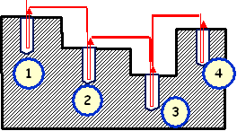
|
Machining Different Depths
When dealing with
design feature holes in design patterns, both the result and
specification mode are taken into account (except Spot Drilling,
Counterboring, and Countersinking operations).
Select the Machine different depths checkbox in
the Geometry tab page when you want the program to automatically
manage different depths of holes in a pattern (result mode).
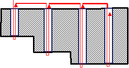
If the checkbox is not selected, the program
uses the values specified in the Geometry tab page for the pattern
holes (specification mode).
For Threading operations,
select the Machine different thread depths checkbox
when you want the program to take the real thread depth of each
selected pattern hole into account.
Note: Different thread depths can be applied only when
information exists on the geometry linked to the machined position.
For example, thread information exists on a threaded design
hole but none exists for a circular edge.
When no thread information exists on the geometry linked to
the machined position, the depth defined on the operation is
used.
|
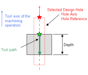
Relimiting Hole Origins
The Relimit hole origin and Machine different
depths checkboxes in the Geometry tab page can be used
together to manage the machining strategy of different design
hole configurations.
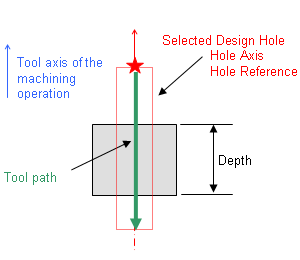
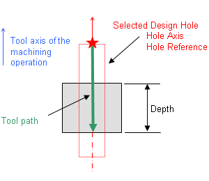
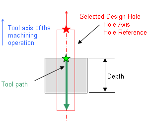
In the following figures the red star ( )
represents the origin of the selected design hole, and the green
star ( )
represents the origin of the selected design hole, and the green
star ( )
represents the start of the tool path. )
represents the start of the tool path.
|
Relimit hole origin Off
Machine different depths Off
|
Relimit hole origin Off
Machine different depths On
|
Relimit hole origin On
Machine different depths Off
|
Relimit hole origin On
Machine different depths On
|
Machining Different Diameters
It is possible
to machine different hole diameters in a Circular Milling
operation thanks to the Machine different diameters
checkbox on the Geometry tab page.
If selected, the diameter specified for each position of
the machining pattern is machined.
Otherwise, the diameter of the first position of the machining
pattern is used for all the pattern holes.
|
Managing Blind and Through
Holes
A Machine Blind/Through
checkbox is provided in the Geometry tab page.
If selected, the blind/through characteristic of the hole
is determined for each position of the machining pattern.
If not selected, the blind/through characteristic of the first
position of the machining pattern is used for all the pattern
holes.
Note that the Machine Blind/Through
capability is not available for user features.
|
Macros in Axial Machining Operations
The Macro tab page
 in the operation definition dialog box allows customized transitions
paths for:
- approach
- retract
- linking linking between machining holes of the same
pattern
- clearance, which can be used to define the feedrate
on the horizontal path between two machining positions.
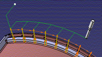
All types of macros used in Drilling
Operations are collision checked. If a check element is specified
between two machined positions, a linking macro is applied to
avoid collisions. Check (or fixture) elements as well as an
associated Offset on Check can be specified in the
Geometry tab page.
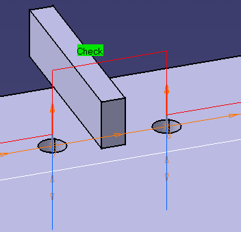
Note that some specific axial machining operations support
additional macro types:
- global approach and global retract (Circular Milling
and Thread Milling)
- return between levels (Circular Milling and Thread Milling)
- return in a level (Circular Milling only).
Please refer to
Define Macros on an Axial Machining Operation for more information.
|
Editing CYCLE Syntaxes in
Axial Machining Operations
For all axial operations Edit Cycle
 in the Axial Machining Operation dialog box allows you to:
- display the unresolved syntax of the NC Instruction
of the operation. This is the syntax as specified in the
PP table referenced by the current Part Operation.
- display and, if needed, modify the syntax that is resolved
either by geometric selection and user entries.
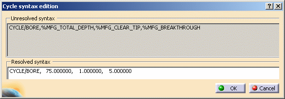
For example, the Cycle Syntax Edition dialog box appears
when you select Edit Cycle
 in the Boring operation dialog box. It displays the default
cycle syntax for the Boring operation.
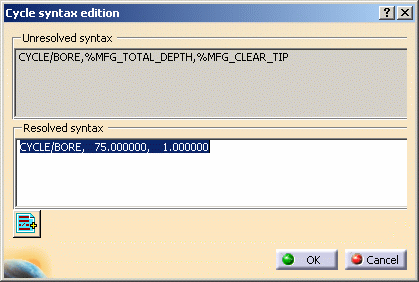
You can access all the cycle syntaxes contained in the current
PP table for a Boring operation by means of PP instruction
 . .
For example, if your PP Table contains the following NC Instructions
for Boring operations:
/
*START_NC_INSTRUCTION NC_BORING_1
*START_SEQUENCE
CYCLE/BORE,%MFG_TOTAL_DEPTH,%MFG_CLEAR_TIP
*END
*END
/
*START_NC_INSTRUCTION NC_BORING_2
*START_SEQUENCE
CYCLE/BORE,%MFG_TOTAL_DEPTH,%MFG_CLEAR_TIP,%MFG_BREAKTHROUGH
*END
*END
/
*START_NC_INSTRUCTION NC_BORING_3
*START_SEQUENCE
CYCLE/BORE,%MFG_TOTAL_DEPTH,%MFG_PLUNGE_OFFST,%MFG_CLEAR_TIP
,%MFG_FEED_MACH,%MFG_FEED_RETRACT
*END
*END
/
*START_NC_INSTRUCTION NC_BORING_4
*START_SEQUENCE
CYCLE/BORE,%MFG_TOTAL_DEPTH,%MFG_PLUNGE_OFFST,0,%MFG_CMP_DWL_TIME,%MFG_CLEAR_TIP
,%MFG_FEED_MACH,%MFG_SPNDL_MACH,ON,0,0,%MFG_FEED_RETRACT
*END
*END
Then these syntaxes will be displayed in the PP Words Selection
dialog box that appears:
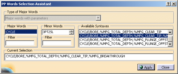
You can then select the desired syntax and click
Apply to display it in the Cycle Syntax Edition dialog
box. Just click OK to use the cycle syntax in the Boring operation
being edited.
Note that in the example above, the PP Table
contained several PP Instructions for the same operation type:
NC_BORING_1 to NC_BORING_4.
Note that only one cycle syntax (delimited by
*START_SEQUENCE / *END keywords) is allowed for
each PP Instruction.
In this way, a multiple choice of syntaxes is
proposed at programming time.
For more information please refer to
Insert PP Instruction.
|
![]() .
.


