Note that you can also create drawings and drawing views from a layout
Printing a Whole Layout Sheet |
|
|
|
Note that you may also print several sheets if a layout contains several of them. |
-
Select File > Print.
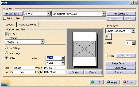
The Print dialog box is displayed.
-
Choose your print options as required:
-
The Printers area lets you choose the printer you want to use or specify whether you want to print to a file.
-
The Layout tab lets you define the sheet orientation, position and size.
-
The MultiDocuments tab lets you specify additional choices if the current document contains several sheets. Refer to Printing Multi-Documents in the Infrastructure User's Guide for more information.
-
The Print Area area lets you define whether you want to print:
-
the entire sheet: Whole Document.
-
the sheet as seen on screen: Display.
-
the area selected using the Selection button
 .
Refer to Printing an
Area of a Layout Sheet below for more information.
 -
the print area previously defined for the sheet: Document area. This print area is defined (and activated) in the sheet properties. Refer to Editing Sheet Properties for more information.
Note that the Document area option appears only if you activated the print area in the sheet properties prior to accessing the Print dialog box.
-
-
The Copies field lets you specify the number of copies to print.
-
The Tiling option lets you tile the sheet and print it on several pages.
-
The Page Setup... button lets you define the page setup.
-
The Options... button lets you define additional options.
-
The Preview... button lets you preview the document to be printed.
-
-
Click OK to print the sheet and close the Print dialog box.
Printing an Area of a Layout Sheet |
|
-
Select File > Print.
The Print dialog box is displayed. -
Choose your print options as required.
-
Choose Selection in Print Area.
This activates the selection mode button and allows you to select the area to print. -
Click the selection mode button
 .
.
-
Drag the cursor on the layout to define the print area.

-
Click OK to print the sheet and close the Print dialog box.
More About Printing |
|
What is printed?
The print functionality usually prints exactly what is visible in the layout window (or, when printing multi-documents, what would be visible in the layout window if the printed sheet was the active one).
However, what is printed sometimes depends on the print mode (raster or vector). For example:
- View filters and the layout view background are always taken into account, independently of the print mode.
- The cutting plane, clipping frame, back-clipping plane are taken into account only when printing in raster mode.
|
|
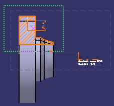
In the case of the clipping frame, the frame itself is not printed. |
You should also know that when printing multi-documents in the context of a .CATProduct, only the sheets of the edited layout (whether part or product) are taken into account.
For more information, refer to the next paragraph Which print mode (raster or vector) is used?.
Which print mode (raster or vector) is used?
Print will be performed using a combination of raster and vector elements, depending on the following factors:
- which print Rendering Mode option you choose (from the Print dialog box: click the Options... button and then the Various tab),
- Display all elements using Z-buffer check box (in Tools > Options > General > Display > Visualization tab) is selected or cleared.
The table below summarizes the possible scenarios.
|
|
In the table below:
|
| With Display all elements using Z-buffer option cleared... | With Display all elements using Z-buffer option selected... | ||
| If the print Rendering Mode option is... | 2D elements are printed in... | 3D elements are printed in... | 2D and 3D elements are printed in... |
| Default | Vector mode | Raster/Vector mode* | Raster mode |
| Wireframe, Hidden Line Removal, Shading with Triangles |
Vector mode | Vector mode | Vector mode |
| Dynamic Hidden Line | Vector mode | Vector mode | Not supported |
*NB: Whether 3D elements are printed in raster or vector mode depends on the view mode of the 2D Layout for 3D Design window, and not on the print rendering mode. 3D elements are printed in raster mode only when there is a shading to draw (for example Shading with edges or Material rendering modes). When there is no shading (for example in Hidden Line Removal or Shading with Triangles), 3D elements are printed in vector mode.
For more information
For detailed information about printing, refer to the the Printing Documents chapter in the Infrastructure User's Guide. Make sure you refer to Customizing Print Settings Before Printing Your Documents. The Printing Multi-Documents task should also be helpful.
![]()