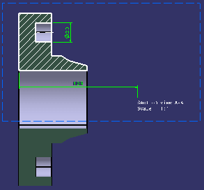
Note that the cutting plane is applied globally to a layout, which means it is either active or inactive for all views at once.
If necessary, activate the Display Backgrounds as Specified for Each View
-
The Cutting Plane
 is
activated
in the Visualization toolbar.
Notice how the 3D background of the Section view is cut along its definition plane.

Click Cutting Plane
 icon in the Visualization
toolbar to activate or deactivate the cutting plane.
 - Now, de-activate the
Cutting Plane
 icon and notice how the 3D background of the Section view is no longer cut along its definition plane.
-
In the Tools > Options > Mechanical Design > 2D Layout for 3D Design, Visualization tab, Background And Cutting Plane field, the Display when loading layout option, is selected by default. This option keeps the Cutting Plane
 activated every time the CATPart containing the 2D Layout is opened.
-
If the cutting plane is deactivated and the 2D Layout window is closed keeping the 3D window open, then again on reopening the 2D Layout window, the cutting plane is still deactivated.
-
If you close both the 2D and 3D window, and launch the CATPart document in 2D Layout for 3D Design, the cutting plane is activated.
-
-
If the Display when loading layout option is cleared, then the user preference of the Cutting Plane
 is applied to all the 2D Layout windows open in
that CATIA session. This setting is further kept when closing CATIA and restored
when restarting CATIA again.
 -
When the Display when loading layout option is cleared, the last setting of CATIA session is applied. If these settings have never been modified (CATIA new install or CATSettings have not been reset) then the default system values are used with the Display Backgrounds as Specified for Each View active and the Cutting Plane display deactivated.
-
When working in Product Structure context, the CATPart document is kept open as long as any Product Structure referencing the CATPart is not closed.
- The cutting plane is taken into account when creating a drawing view. For more information, refer to the 2D Layout for 3D Design user's guide.
- For more information on the other visualization-related options available in the Visualization toolbar, refer to the Layout Tools task in the 2D Layout for 3D Design user's guide.
![]()