In a second phase, the program has scanned the part, looking for planar faces associated to any kind of feature found in the part. Those faces have been colored in blue.
Mechanical Modeler |
Marking Up Topology in a Part DocumentFinding fillets and planar faces within a Part document |
|
| Use Case | ||
AbstractThis article discusses the CAAMmrFeatureTopoBRep use case. This use case explains how to open a Part document, navigate its mechanical features content to find and modify graphically the fillets it contains. In a second step, all planar faces that are found in the Part representation are also graphically marked up. |
This use case is about scanning an existing Part document, looking for and changing the appearance of some of its content.
|
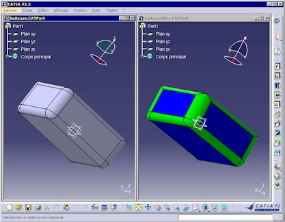
This picture represents a Part document before (left) and after (right)
its processing by the use case. The program has looked for all fillet type
features in the model and extracted the faces associated to them in the
underlying topological model in order to color them in green.
In a second phase, the program has scanned the part, looking for planar faces associated to any kind of feature found in the part. Those faces have been colored in blue. |
In this use case, you will learn how to use two different techniques to browse through the mechanical modeler that manages the internal structure of a Part document:
[Top]
CAAMmrFeatureTopoBRep is a use case of the CAAMechanicalModeler.edu framework that illustrates MechanicalModeler framework capabilities.
[Top]
The job of CAAMmrFeatureTopoBRep is divided into several steps:
[Top]
To launch CAAMmrFeatureTopoBRep, you will need to set up the build time environment, then compile CAAMmrFeatureTopoBRep along with its prerequisites, set up the run time environment, and then execute the use case [2]. To launch the use case, execute the following command:
mkrun -c "CAAMmrFeatureTopoBRep FilenameIn FilenameOut"
where
CAAMmrPadFilled.CATPart located:
InstallRootDirectory/CAAMechanicalModeler.edu/InputDataInstallRootDirectory\CAAMechanicalModeler.edu\InputDataFilenameOut is the complete path of a Part document which
will contain the FilenameIn document modified[Top]
The CAAMmrFeatureTopoBRep use case is made of a single source file named CAAMmrFeatureTopoBRep.cpp located in the CAAMmrFeatureTopoBRep.m module of the CAAMechanicalModeler.edu framework:
| Windows | InstallRootDirectory\CAAMechanicalModeler.edu\CAAMmrFeatureTopoBRep.m\ |
| Unix | InstallRootDirectory/CAAMechanicalModeler.edu/CAAMmrFeatureTopoBRep.m/ |
where InstallRootDirectory is the directory where the CAA CD-ROM
is installed.
[Top]
There are eight logical steps in CAAMmrFeatureTopoBRep:
[Top]
int main(int iArgc,
         char **iArgv) // iArgv[1]: path to an existing Part document
                       // iArgv[2]: path to a  new, modified Part document
{
  // return code
  int rc = 0;

  // Checks number of arguments
  if( 3!=iArgc )
    return 1;

  // Loads input Part and make it ready
  char *pSessionName = "Sample session";
  CATSession *pSession = 0;
  HRESULT rc = ::Create_Session(pSessionName, pSession) ;
  if( SUCCEEDED(rc) )
  {
    CATDocument *pDoc = 0;
    rc= CATDocumentServices::Open(iArgv[1], pDoc) ;

...
|
This section represents the classical sequence for opening a document [3].
[Top]
...
    if( SUCCEEDED(rc) )
    {
        CATInit *pDocAsInit = 0;
        rc= pDoc->QueryInterface(IID_CATInit, (void**)&pDocAsInit) ;

        CATIPrtContainer *pSpecContainer =
              (CATIPrtContainer*)pDocAsInit->GetRootContainer("CATIPrtContainer");
        ...
        CATIPrtPart_var spPart ( pSpecContainer->GetPart() );
        ...
...
|
We readily use the CATIPrtContainer to access the object representing the part through the Part parsing interface, CATIPrtPart.
[Top]
...
// Gets the fillet features
          CATLISTV(CATISpecObject_var) filletFeatures;
          CATIDescendants *pPartAsDescendant = 0;
          rc = spPart->QueryInterface(IID_CATIDescendants, (void**)&pPartAsDescendant);
          if( SUCCEEDED(rc))
          {
            pPartAsDescendant->GetAllChildren("CATIFillet", filletFeatures);
...
|
In this code section we get the CATIDescendants interface that we need
on the Part, and use it to retrieve all Fillet type features within the Part,
regardless of the geometrical features sets in which they are found. CATIDescendants::GetAllChildren
retrieve all features beneath the Part, which implement the interface whose name
is specified as first argument. This search is done regardless of the depth at
which those features are found in the tree. In contrast, CATIDescendants::GetDirectChildren
would have retrieved only those features which are aggregated one level below
the Part. Since we are there at Part level, this would have not retrieved any
Fillet, because such features are not directly aggregated under the Part, but
within geometrical features sets [4].
Since we use here a CATIDescendants interface which is implemented at
the Part level, we perform a multi-sets search. If the search was to be
limited to a single set, then we would have had to QueryInterface
this particular set for its implementation of CATIDescendants and use it
in the same way.
[Top]
...
            for(int currentFillet=1; currentFillet<=filletFeatures.Size(); currentFillet++)
            {
              // Gets the BRep associated with the fillet
              CATIMfGeometryAccess *pFilletAsGeomAccess = 0;
              rc = filletFeatures[currentFillet]->QueryInterface(IID_CATIMfGeometryAccess,
                                                                 (void**)&pFilletAsGeomAccess);
              if( SUCCEEDED(rc))
              {
                CATLISTV(CATBaseUnknown_var) filletBReps;
                pFilletAsGeomAccess->GetBReps(filletBReps);
...
|
We are now entering the loop on all Fillet that will change the color for each of them. We are using a CATIMfGeometryAccess interface that each features that evaluates to a topological results (that is, most of them) implements.
CATIMfGeometryAccess mission is to allow a feature to get access to
all or some of the cells that are part of the Topological Body that represents
its. This is done through two methods, CATIMfGeometryAccess::GetBReps
and CATIMfGeometryAccess::GetCells that exist within the interface
with many different signature to allow more or less filtering on the set of
accessed cells.
Actually, this access to cells is granted by CATIMfGeometryAccess at two different level, the topological level and the scope level. Scopes are management objects that exist within the mechanical world to ensure a Cell-level and stable bi-directional access from Mechanical features to Topological Cells. Scopes are made of nodes (sometimes called Selecting Objects), each associated with a different Cell in the Topological world (for more information on scopes, nodes, cells and the mapping from Mechanical features to Topology, see [5]).
CATIMfGeometryAccess::GetCells provides a direct access to cells
within the Topological world, while CATIMfGeometryAccess::GetBReps
retrieve their counterparts as nodes (or Selecting Objects) within scopes.
Here we use CATIMfGeometryAccess::GetBReps, retrieving a set of
nodes as the result of the shape of the current Fillet feature. The signature
used here is the most simple: it retrieves all nodes associated to the
evaluation of the Fillet.
However, some other features like the Pad, for instance, have characteristic
cells (resp. nodes) in their result, like the "top" face, or the face
that has extruded from a given section of their base sketch. This is why other
signatures for CATIMfGeometryAccess::GetCells and CATIMfGeometryAccess::GetBReps
exist: they allow such Faces (resp. nodes) to be easily retrieved by specifying
such semantic characterization of what is looked for.
[Top]
...
   // Colorizes BRep
                for(int currentBRep=1; currentBRep<=filletBReps.Size(); currentBRep++)
                {
                  CATIVisProperties *pFilletBrepAsGraphics = 0;
                  rc =  filletBReps[currentBRep]->QueryInterface(IID_CATIVisProperties,
                                                                 (void**)&pFilletBrepAsGraphics);
                  if (SUCCEEDED(rc))
                  {
                    CATVisPropertiesValues color;
                    color.SetColor(0, 255, 0); // green
                    pFilletBrepAsGraphics->SetPropertiesAtt(color, CATVPColor, CATVPMesh);
                    pFilletBrepAsGraphics->Release();
                    pFilletBrepAsGraphics = NULL;
                  }
                }
                pFilletAsGeomAccess->Release();
                pFilletAsGeomAccess = NULL;
              }
            }
            pPartAsDescendant->Release();
          }
...
|
We are now going to loop through all the nodes that are associated with the current Fillet in order to set the colors of its associated cell to green.
At this point, we may raise an interesting question. In the previous step, we
have used CATIMfGeometryAccess::GetBReps in order to retrieve nodes
to work upon. We saw that, using CATIMfGeometryAccess::GetCells we
could have retrieved cells instead. Question is, why is it better to colorize nodes rather than
cells, if the two actually represent an access to the same
topological object?
The answer is, coloring nodes is better since it allows the color to be persistent at the Mechanical Modeler level. We are now going to discuss this point.
The Mechanical Modeler manages colors. A Body, a single feature can be assigned a color interactively: no big deal. The Mechanical Modeler allows even a finer grain coloring scheme: by selecting a given face in a multi-faces Fillet, either directly or through the "Other Selection..." local menu, an access to a single face can be obtained, allowing the coloring to affect only that particular face.
Within the Topological Modelers, too, colors are managed (call it a tribute to marketing from mathematicians). Therefore, a cell can be assigned a color. However, the color specifications managed by the Mechanical Modeler override the ones existing at the Topological Modeler level. With this approach, many cells representing a single feature can be colored at once by specifying the color at the feature level, rather that for each cell, which is more efficient. This is done without losing the capacity of single cell coloring, by letting nodes be assigned colors as well. This works well because nodes pertain to the Mechanical world, therefore their individual color can be taken into account in the general visualization mechanism of the Mechanical Modeler.
A last, and more simple approach, could have been used here: assigning colors directly to the Fillet features. This is not done so in this Use Case because the way we do it provides the opportunity to visit and study more interesting code in the Mechanical Modeler code.
So, back to our code snippet. What we actually do here is to get an interface
on the node, that allows to change its graphics properties. This interface is CATIVisProperties.
We use its SetColor method to paint all cells associated to the
current node in the loop in green.
[Top]
Now that the fillets have been colored in green, the second part of the job consists in coloring the planar faces in blue. The goal of this section is the following:
You can refer to the technical article entitled "Specification/Result Mechanism Applied to Mechanical features" for more details about the result feature [6]. This article explains that the association of the topological body to a geometrical features set is actually managed by a specialized feature, sometimes called the result feature.
...
   CATIPartRequest_var spPartRequest = spPart ;
   ...
   CATBaseUnknown_var spMainPartBody ;
   rc = spPartRequest->GetMainBody("",spMainPartBody);

...
|
GetMainBody of the CATIPartRequest interface retrieves
the main Body feature of a Part document. It is a feature instantiated from
the HybridBody StartUp [4].
...
   CATIBodyRequest_var spMainPartBodyBodyRequest = spMainPartBody ;
   ...
   CATLISTV(CATBaseUnknown_var) ListResult ;
   rc = spMainPartBodyBodyRequest->GetResults("",ListResult);
   ...
   CATIGeometricalElement_var spFeatureResultGeomElem = ListResult[1] ;
...
|
The CATIBodyRequest interface, implemented on HybridBody StartUp, enables you to retrieve the result feature. This feature is a Solid
feature which bears the topological result [6]. The
first element of ListResult, is the feature result itself.
... CATBody_var spPartTopoBody = spFeatureResultGeomElem->GetBodyResult(); ... |
The GetBodyResult method applied to the result feature of the
Body feature returns the topological result to process.
... CATLISTP(CATCell) cells; spPartTopoBody->GetAllCells(cells, 2); ... |
From spPartTopoBody, the topological body, a list of all its
topological cells can be obtained through GetAllCells. Here the
cells are filtered out, keeping only the 2 dimensional cells, i.e. faces.
[Top]
...
          for(int currentCell=1; currentCell<=cells.Size(); currentCell++)
          {
            CATGeometry *pGeometry = cells[currentCell]->GetGeometry();
            if ( (NULL != pGeometry) && (pGeometry->IsATypeOf(CATPlaneType)) )
            {
              CATCell_var pCell ( cells[currentCell] );
              CATIBRepAccess_var spBRepAccess ( CATBRepDecode(pCell, spFeatureResultGeomElem) );
              if( NULL_var!=spBRepAccess )
              {
                // Colorizes BRep
                CATIVisProperties *pBRepAccessAsGraphics = 0;
                rc = spBRepAccess->QueryInterface(IID_CATIVisProperties,
                                                  (void**)&pBRepAccessAsGraphics);
                if( SUCCEEDED(rc))
                {
                  CATVisPropertiesValues color;
                  color.SetColor(0, 0, 255); // Blue
                  pBRepAccessAsGraphics->SetPropertiesAtt(color, CATVPColor, CATVPMesh);
                  pBRepAccessAsGraphics->Release();
                  pBRepAccessAsGraphics = NULL ;
                }
...
|
What's next? Painting the cells associated with the planar faces in blue. We got those cells in the cells collection, so we loop over it in search of planar faces.
To check if a face is planar, we get from it an object of type CATGeometry,
which bears its geometrical description. CATGeometry::IsATypeOf
allows to discriminate among several geometry types, among which CATPlaneType
for planar entities.
One last trick. Remember that we said earlier that we wanted to place our coloring attribute at the Mechanical Modeler level, otherwise it would be at risk of being overridden. However, our search for the faces that are planar has necessarily taken place at the Topological Modeler level, where such geometrical properties are maintained and can be queried. So what we have so far is a list of topological cells that we know as planar. What we want is to find their corresponding Mechanical Modeler entity.
This Mechanical Modeler entity is not a mechanical feature, because actually what we want to paint are part of features (individual faces). They actually are a node, which is the element in the Mechanical Modeler responsible of managing the link with a topological cell that represents part of the resulting shape associated with the evaluation of a mechanical feature. More or nodes and the link between Mechanical and Topological Modeler in [5].
So what we do here is using the CATBRepDecode function for
retrieving the node object that is associated, in the result feature that
represents the evaluation of our Body feature (spFeatureResultGeomElem),
with the cell we found planar.
The resulting node implements the CATIVisProperties interface, which is used to change its color.
[Top]
...
   // Saves the part document
   CATDocumentServices::SaveAs(*pDoc, iArgv[2]);

   // Closes the document
   CATDocumentServices::Remove(*pDoc);
  }
  else
  {
    cerr << "doc not opened" << endl;
    rc = 1;
  }

  // Deletes all documents in session
  ::Delete_Session(pSessionName);
}
...
|
In the epilog of the use case, we save the modified Part as a new document under the file path entered on the command line, close the document from session and delete the session, in a way symmetrical to what we did in the prolog. Refer to [3] for details.
[Top]
In this use case we are interested in coloring specific details of a Part, based on two different criteria: feature nature (fillets) or a geometrical property (planarity of faces). This requires two strategies, depending upon whether or not we need to descend at the Topological Modeler level to find what we look for.
Finding fillets requires only a search at the Mechanical Modeler level. The CATIDescendant interface is used at the part level to filter out all features in the Part that have the 'fillet' type. Then the CATIMfBrepAccess interface is used to retrieve all nodes that manage the links to the Topological Modeler cells that represent the fillet. Implementation by nodes of the CATIVisProperties is used to set the color in a way that guarantees that the new color will be persistent at the Mechanical Modeler level.
The search for planar faces is different in that it requires the help of the underlying Topological Modeler to sort out planar from non planar cells. So first all cells associated with the main Body feature are requested, and then they are tested for planarity by accessing their geometry and querying it for planarity. With planar cells only left, the decoding mechanism is invoked, so as to relocated in the Mechanical Modeler the nodes associated to the selected cells. Then those nodes are colored in the same way than fillet were in the first part of the use case.
[Top]
| Version: 1 [Jan 2000] | Document created |
| Version: 2 [Sep 2003] | Finding Out the Planar Faces section modified |
| [Top] | |
Copyright © 2000, Dassault Systèmes. All rights reserved.