Main domains linked to the Drafting application
Added value of the Drafting modeler
Mechanical Design |
Drafting |
Drafting Modeler OverviewDescribing the foundations of the Drafting Modeler |
| Technical Article | ||
AbstractThis article discusses the Drafting modeler foundations. |
The Drafting application is in relation with several domains. The Drafting modeler enables you to automate tasks linked to these domains. See below the added value of the Drafting modeler.
|
|
|
Main domains linked to the Drafting application
|
|
|
|
Added value of the Drafting modeler
|
The Drafting modeler manages geometry, constraint, annotation, dress-up and structuring objects (Sheet, View, Detail Sheet, Ditto). All elements created by the Drafting modeler are fully integrated in the Drawing document. That means, they will recognized by internal mechanism such as sketcher picking assistant, dimensioning, associative orientation and positioning and constraints.
|
|
The Drafting workbench is loaded and the current drawing sheet (Sheet.1) opens. The drawing specification tree is displayed to the left of the sheet. This tree shows aggregations between structuring objects. "Front View" view of "Sheet.1" sheet is the active view of the active sheet: That means all elements created by indication will be aggregated on this view. At the top of the document, a tab page manages the active sheet.
|
A drawing document is a collection of sheets, along with information on the drafting standard (ISO, ANSI, ASME and JIS).
The sheet corresponds to the paper space, where the following elements are positioned:
The view may contain:
[Top]
The drafting application is managed by two products:
These two products are prerequisite to develop an application based on Drafting modeler.
Two frameworks contain the drafting modeler API:
[Top]
The drawing application data is included in an applicative container: the
drawing container may be obtained from drawing root by using
GetFeatContainer method [1].
When a drawing document is created, the following objects are created at the same time:
The following steps are necessary to complete the drawing creation:
The CATIDrwFactory interface implemented on drawing container enables you to create views or sheets and any objects which are not aggregated by a view. for example sheet, view, pattern, detail or relations.
Note: To create a sheet, it is better to use the AddSheet
method of the CATIDftDrawing interface to take into account the sheet page
manager [1].
A sheet aggregates views and a view aggregates all objects instantiated in it. There is always an active view in a sheet. To create objects directly in a sheet, the main view of the sheet has to be activated.
|
|
|
This figure shows the UML diagram of drafting structuring objects. |
A view inherits from sketch to manages 2D geometry and 2D constraints. Two kinds of geometry coexist in a view:
Two kinds of interfaces allow to get information on geometry:
[Top]
A 2D component is a re-usable set of geometry and annotations. This component is located in a sheet and can be edited like a view. This is why this component is called Detail View. The 2D component can be instantiated several times, each instance providing a component with a specific orientation, position and scale. The detail view can be either in the same drawing as the CATDrawing of the corresponding instances or in a separate CATDrawing.
The Catalog Browser command allows to instantiate a ditto from an external CATDrawing document CATDrawing1 in a new Drawing document CATDrawing2. To do that, a special copy of Detail Ref is created (Detail Ref2) and an instance of this copy (Ditto Inst 1). Detail Ref2 Detail is a no accessible local reference of the Reference Detail (Detail Ref). See figure 1.
|
Figure 1 |
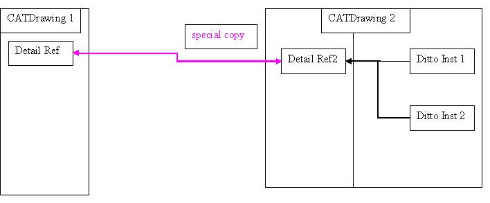 |
Detail Ref 2 can not be directly modified. Only Detail Ref can be modified. When you instantiate for the second time the ditto (from Detail Ref) , in the new CATDrawing CATDrawing 2, a new instance of the “copied” detail (Detail Ref2) is created (Ditto Inst 2).
No object can be modified in Ditto instance except Text modifiable in instance.
Text modifiable in instance:
A modifiable text in instance is a text with a specific attribute to inform the system to duplicate the text when a ditto is instantiated. See under the way to access to modifiable objects in instance:
// GetModifiableObjects method allows to retrieve texts modifiable in ditto piDitto CATIADrawingComponent * piMyDrawComp = NULL;
HRESULT rc = piMyDitto -> QueryInterface (IID_CATIADrawingComponent,(void**)&piMyDrawComp);
if ( SUCCEEDED(rc) )
{
long Count = 0;
piMyDrawComp -> GetModifiableObjectsCount (Count);
for ( int Idx = 1; Idx<=Count; Idx++ )
{
CATVariant Variant;
rc = BuildVariant ((long)Idx, Variant);
if ( SUCCEEDED(rc) )
{
CATIABase * piABase = NULL;
rc = piMyDrawComp -> GetModifiableObject (Variant, piABase);
if ( SUCCEEDED(rc) )
{
|
[Top]
These objects are created by using 2D wire frame factory defined in
SketcherInterface framework. A pointer on CATI2DWFFactory interface may
be obtained by using a QueryInterface on the view [1].
Notes:
SaveEdition method defined on
CATISketchEditor interface has to be executed. CATISketch
interface inherits from CATISketchEditor, so, SaveEdtion
may be executed from
CATISketch
interface.[Top]
These objects are created by using 2D constraint factory defined in
SketcherInterface framework. A pointer on CATI2DConstraintFactory
interface may be obtained by using a QueryInterface on the view.
In this factory
CreateConstraint method allows to create constraint in the view.
[Top]
These objects are created by using drawing annotation factory. A pointer on
CATIDrwAnnotationFactory interface may be obtained by using a
QueryInterface on the view [2].
All the annotations inherit from AnnotationComponent object which inherits from
Annotation object. CATIDrwAnnotation interface manages associative
position and associative orientation between annotations or annotation and
geometry. CATIDrwAnnotationComponent is dedicated to manage global informations
relative to the annotation text.
When an annotation is modified feature has to be rebuild to get the result [3].
|
|
|
This figure shows the UML diagram of annotation objects
|
[Top]
These objects are created by using drawing annotation factory. A pointer on
CATIDrwAnnotationFactory interface may be obtained by using a
QueryInterface on the view. Sometime these elements require geometry to
be created. The Center Line Creation sample explains how to create center line
from 2D geometry or Generative Geometry [4].
[Top]
These views are created from 3D data coming from Product or Part type documents. To create a Generative Front View, a view with makeUp first has to be created, then the view typed by using the SetViewType method defined in CATIView interface. The SetDoc method allows to create a link between the Generative View and the 3D document. At last, define a projection plane in the view using the SetProjectionPlane method of the CATIGenerSpec interface. A pointer to CATIGenerSpec interface may be retrieved from CATIView interface by using GetGenerSpec method. As any view, a Generative View has to be aggregated to a sheet by using AddView method on CATIDftSheet interface. To get the result of a 3D projection in the view, call the Update method on CATIView interface.
Particular Generative views may be easily created by using the following interface: CATIDftGenViewFactory interface. This interface is implemented by the sheet object:
[Top]
These objects are automatically created when a Generative View is created or updated. Generative Geometry is defined from 3D Document and associated on it. Generative Geometry can not be edited, only graphic properties may be modified [8].
[Top]
The CATIDrwAddIn interface enables you to add a new command in drafting workbench. Interactive commands defined in CAADraftingInterfaces.edu framework have been plugged in a toolbar [9].
The CATIDftMultiSheet interface, implemented by the sheet enables to keep an interactive command active when the active sheet is changing [10].
[Top]
This article has explained the foundations of the Drafting Modeler.
[Top]
| Version: 1 [Mar 2004] | Document created |
| [Top] | |
Copyright © 2004, Dassault Systèmes. All rights reserved.