Mechanical Design |
Drafting |
Creating Center Lines in a CATDrawing DocumentHow to create annotations on interactive or generative geometry |
| Use Case | ||
AbstractThis article discusses the CAADrwCenterLine use case. This use case explains how to create center lines on interactive or generative geometry in a CATDrawing document. |
In this use case you will learn how to create annotations (center lines) on interactive and generative geometry.
[Top]
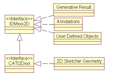
There are two levels of interfaces:
|
The IDM interfaces are standard interfaces (Interfaces for Design and Modeling). IDMs may be re-implemented for user-defined objects. This is the way to integrate those elements in:
[Top]
CAADrwCenterLine is a use case of the CAADraftingInterfaces.edu framework that illustrates DraftingInterfaces framework capabilities.
[Top]
This use case is made of a state command that waits for a selection and creates center lines on selected circles.
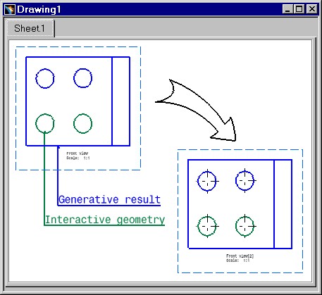 |
This picture represents two views :
[Top]
To launch CAADrwCenterLine, you will need to set up the build time environment, then compile CAADrwCenterLine and CAADrwAddin along with its prerequisites, set up the run time environment.[1].
Top]
The CAADrwCenterLine use case is made of two source files named CAADrwCenterLine.h and CAADrwCenterLine.cpp located in the CAADrwCenterLine.m module of the CAADraftingInterfaces.edu framework:
| Windows | InstallRootDirectory\CAADraftingInterfaces.edu\CAADrwCenterLine.m\ |
| Unix | InstallRootDirectory/CAADraftingInterfaces.edu/CAADrwCenterLine.m/ |
where InstallRootDirectory is the directory where the CAA CD-ROM
is installed.
[Top]
There are two steps in CAADrwCenterLine:
[Top]
void CAADrwCenterLineCmd::BuildGraph()
{
   // Creation of the acquisition agent
   _ObjectAgent = new CATPathElementAgent("_ObjectAgent A");
   _ObjectAgent ->SetBehavior( CATDlgEngWithPrevaluation |
                               CATDlgEngMultiAcquisition |
                               CATDlgEngWithCSO);

   // We only want to get circles
   _ObjectAgent ->AddElementType("IDMCircle2D");
   AddCSOClient(_ObjectAgent);

   //  States definition
   CATDialogState* pState1 = GetInitialState("Sel circle");
   pState1->AddDialogAgent(_ObjectAgent);

   // Transition definition
   AddTransition(pState1, NULL, IsOutputSetCondition(_ObjectAgent),
                 Action((ActionMethod)&CAADrwCenterLineCmd::CreateCtrLine, NULL, NULL));
}
|
In this section we create a CATPathElementAgent and set the corresponding element type to IDMCircle. So only circles could be selected [2].
[Top]
boolean CAADrwCenterLineCmd::CreateCtrLine(void *iData)
{
   CATSO* pObjSO = _ObjectAgent->GetListOfValues();
   CATPathElement *pElemPath = NULL;

   if (NULL != pObjSO)
   {
      // We will scan the CSO from the begining
      pObjSO->InitElementList();
      while (NULL != (pElemPath = (CATPathElement*)pObjSO->NextElement())  )
      {

         // Make sure the element is a circle type
         // This circle can be interactive or a generative result (from part, model, ...)
         IDMCircle2D *piElementRef = (IDMCircle2D *)pElemPath->FindElement(IID_IDMCircle2D);

         if (NULL != piElementRef)
         {
            // Find the annotation factory (on the view)
            CATIDrwAnnotationFactory *piDrwFact = (CATIDrwAnnotationFactory *)pElemPath->FindElement(IID_CATIDrwAnnotationFactory);
            if (NULL != piDrwFact)
            {
               // Let's create the center line
               piDrwFact->CreateDrwCenterLine((CATBaseUnknown *)piElementRef);
               piDrwFact->Release();
            }
            piElementRef->Release();
         }
      }

      _ObjectAgent -> InitializeAcquisition();
      return TRUE;
   }
   return FALSE;
}
|
The acquisition agent did put the selected circles into the CSO. So we get the SO and loop on it. The selected circles can be generative ones or interactive ones. We get the annotation factory on the view and call the center line factory method giving the circle as argument.
[Top]
This use case shows how to create a state command dealing with geometry selections. The IDMxx2D interfaces identificators are used as filters and allows the selection of interactive and generative geometry. Using the CATIDrwAnnotationFactory, interface, implemented by the view, it is possible to create annotations on these geometries.
[Top]
| [1] | Building and Lauching a CAA V5 Use Case |
| [2] | Implementing the Statechart Diagram |
| [Top] | |
| Version: 1 [Jan 2000] | Document created |
| [Top] | |
Copyright © 2000, Dassault Systèmes. All rights reserved.