3D PLM Enterprise Architecture |
User Interface - Commands |
Implementing the Statechart DiagramCoding the BuildGraph method |
| Use Case | ||
AbstractThis article shows how to retrieve a point in the 3D space from an end user mouse click on the screen in a state dialog command. |
This use case is intended to show how to implement the statechart diagram of
a state dialog command by coding the command BuildGraph [1]
method. BuildGraph is the command core. It declares the objects
that make up the dialog steps and sequences, and their relationships.
[Top]
The Rectangle command is a use case of the CAADialogEngine.edu framework that illustrates the DialogEngine framework capabilities.
[Top]
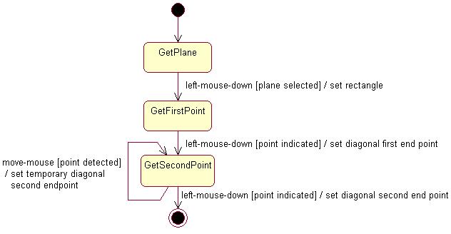
CAACreateRectangleCmd is a state dialog command that creates a rectangle in the 3D space according to the following UML statechart diagram [2].
The dialog is as follows:
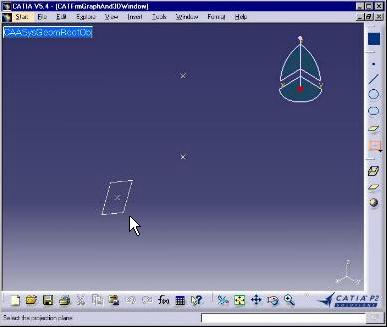 |
Select the CAADegCreateRectangleCmd command. The active state is GetPlane. Select an existing plane that will be used as the rectangle plane. The selection is possible thanks to a selection agent. |
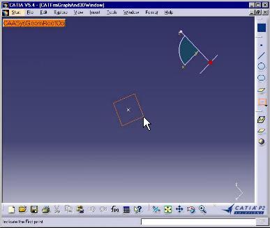 |
The viewpoint changes to make the selected plane and the screen plane coincide. The active state becomes GetFirstPoint. |
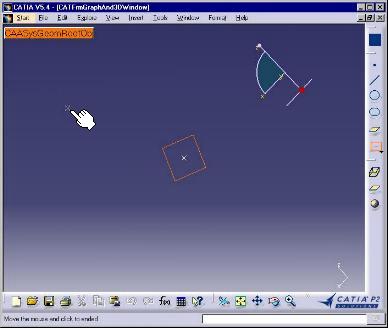 |
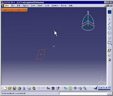
Click to indicate a point for the diagonal first end point. The active state becomes GetSecondPoint. This image is captured just after the click. The indicated point is shown beside the plane. The mouse has not yet moved. The indication is enabled thanks to an indication agent. |
 |
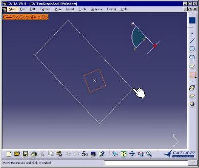
Move the mouse from this point. A temporary rectangle is drawn and increases or decreases to follow the mouse moves. The active state remains GetSecondPoint. The self transition loops onto this state. The indication is enabled thanks to the second indication agent. |
 |
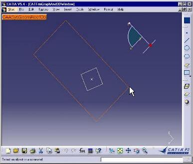
Still moving the mouse, the temporary rectangle go on increasing or decreasing to follow the mouse moves. The active state remains GetSecondPoint thank sto the self transition that loops onto this state. The indication remains enabled thanks to the second indication agent. |
 |
When the wished rectangle is obtained, click to create the diagonal second end point. This creates the rectangle. The indicated point is retrieved thanks to the second indication agent. The command is now complete. |
The Rectangle command statechart diagram comprises three states in addition
to the initial and final states, and four transitions including a self
transition that loops onto a state to create a temporary rubber rectangle.
Dialog agents with appropriate types and behaviors, associated with the states,
make it possible to convert the end user input into stimuli that trigger the
transitions and to retrieve the end user interaction intent, that is selecting
an object for a selection agent [3] or indicating a
point for an indication agent [4]. To simplify the BuildGraph
method, undo/redo [5] is not taken into into account.
[Top]
See the section entitled "How to Launch the CAAGeometry Use Case" in the "The CAAGeometry Sample" use case for a detailed description of how this use case should be launched.
Then, in the window where you run the mkrun command, do not type the module name on the command line, but type CNEXT instead. When the application is ready, do the following:
[Top]
The Rectangle command is made of a single class named CAADegCreateRectangleCmd located in the CAADegGeoCommands.m module of the CAADialogEngine.edu framework:
| Windows | InstallRootDirectory\CAADialogEngine.edu\CAADegGeoCommands.m\ |
| Unix | InstallRootDirectory/CAADialogEngine.edu/CAADegGeoCommands.m/ |
where InstallRootDirectory is the directory where the CAA CD-ROM
is installed.
[Top]
To create the CAACreateRectangleCmd BuildGraph method, there are three steps:
| # | Step | Where |
|---|---|---|
| 1 | Create the dialog agents | BuildGraph method |
| 2 | Create the states | BuildGraph method |
| 3 | Create the transitions between the states | BuildGraph method |
[Top]
The BuildGraph methods starts by creating the dialog agents.
Pointers to dialog agents are data members of the state dialog command, because
they are often used in several condition and/or action methods in addition to
BuildGraph. The first one is a selection (path element) agent to select the
rectangle underlying plane.
void CAADegCreateRectangleCmd::BuildGraph()
{
  //1- Creates the dialog agents

  //1-1 Dialog agent to select the rectangle plane
  _daPathEltPlane = new CATPathElementAgent("SelPlane");
  _daPathEltPlane->AddElementType("CAAISysPlane");

  // To enable agent prevaluation, plane prehighlight and highlight
  // No Undo step recorded for this agent
  _daPathEltPlane->SetBehavior(CATDlgEngWithPrevaluation |
                               CATDlgEngWithPSOHSO |
                               CATDlgEngWithUndo);
  // Let _daPathEltPlane be valued from the CSO
  AddCSOClient(_daPathEltPlane);
...
|
This code portion has the following meaning:
SelPlane
is the dialog agent identifier that could be used if an undo step were
recorded. Even if this is not the case here, the identifier is requestedAddElementType method, the selection agent is
valued only when an object that implements the CAAISysPlane interface is
selected. The selection agent remains impassive when any object that doesn't
implement this interface is selectedSetBehavior
method. The global behavior is made of a concatenation of unit behaviors set
using keywords separated with the "|" pipe character
CATDlgEngWithPrevaluation means that the selection agent
is prevalued when an object is preselected, that is, as long as the
mouse moves or is located above the object without left clicking. The
object must of course match the type set by AddElementType,
otherwise the dialog agent is not prevaluedCATDlgEngWithPSOHSO means that any preselected object is
prehighlighted, and thus put in the PSO (Prehighlighted Set of Objects),
and that any selected object is highlighted, and thus put in the HSO
(Highlighted Set of Objects)CATDlgEngWithUndo means that no undo step is recorded for
this dialog agent [x]AssCSOClient method
enables the dialog agent to be valued if the CSO (Current Set of Objects)
contains such an object when the command is selected, this object being put
in the CSO before the command selection either by an end user selection or
as a result of the preceding command. This is a powerful means to increase
end user productivity.The second dialog agent is an indication agent used to get the rectangle diagonal first end point.
...
  //1-2 Dialog agent to indicate the rectangle diagonal first end point
  _daIndicationP1 = new CATIndicationAgent("IndicationP1");
  // No Undo step recorded for this agent
  _daIndicationP1->SetBehavior(CATDlgEngWithUndo);
...
|
Its identifier is set as the argument of its constructor, even if it will be useless since no undo step is recoreded.
The third dialog agent is an indication agent used to get the rectangle diagonal second end point.
...

  //1-3 Agent to indicate the rectangle diagonal second end point
  _daIndicationP2 = new CATIndicationAgent("IndicationP2");
  // To enable agent prevaluation, and transition to trigger on prevaluation
  // No Undo step recorded for this agent
  _daIndicationP2->SetBehavior(CATDlgEngWithPrevaluation |
                               CATDlgEngAcceptOnPrevaluate |
                               CATDlgEngWithUndo);
...
|
Its behavior enables prevaluation, like with the selection agent. In addition
CATDlgEngAcceptOnPrevaluate means that prevaluation is enough to
trigger a transition, while usually it is not.
[Top]
The states are created in the order where they appear in the statechart diagram, and the dialog agents are immediately associated to them. They can be created on the stack.
...
  //2- Creates states. See Nls file
  CATDialogState *stPlaneState = GetInitialState("stPlaneStateId");
  stPlaneState->AddDialogAgent(_daPathEltPlane);

  CATDialogState *stGetFirstPointState = AddDialogState("stGetFirstPointStateId");
  stGetFirstPointState->AddDialogAgent(_daIndicationP1);

  CATDialogState *stGetLastPointState = AddDialogState("stGetLastPointStateId");
  stGetLastPointState->AddDialogAgent(_daIndicationP2);
...
|
The first state is created using the GetInitialState method that
also create an automatic transition fromthe initial state to this state, while
the others are created using the AddDialogState method. Each state
is assigned an identifier used to set a prompt displayed in the status bar when
the state is active. The AddDialogAgent method associates dialog
agents with states.
[Top]
Still in the BuildGraph method, the last thing to do is to
create the transitions. They can also be created on the stack. The first
transition links the states that requests the rectangle plane and the rectangle
diagonal first end point.
...
  //3- Creates transitions
  CATDialogTransition *pFirstTransition = AddTransition(
    stPlaneState,
    stGetFirstPointState,
    IsOutputSetCondition(_daPathEltPlane),
    Action((ActionMethod) & CAADegCreateRectangleCmd::CreateCamera)
  );
...
|
Transitions are created using the AddTransition method using the
following arguments:
stPlaneState is the transition source statestGetFirstPointState is the transition target stateIsOutPutSetCondition that acts as the
transition trigger, since it returns True if the selection agent is valued,
and False otherwise. No other condition is set, for example on the selected
objectThe second transition links the two rectangle diagonal end point indication states.
...
  CATDialogTransition *pSecondTransition = AddTransition(
    stGetFirstPointState,
    stGetLastPointState,
    AndCondition(IsOutputSetCondition(_daIndicationP1),
                 Condition((ConditionMethod)& CAADegCreateRectangleCmd::TestPoint1)),
    Action((ActionMethod) & CAADegCreateRectangleCmd::CreatePoint)
  );
...
|
The two states are the first two arguments. A composite condition is used as the transition guard condition, and a member function is used as the transition action. The composite condition is a CATBoolean AND between two condition return values:
IsOutputSetCondition method that returns True if the
indication agent is valuedTestPoint1 that
returns True if a point can be created in the document.The third transition is a self-transition that loops on the state that asks for the diagonal second end point. This transition creates a temporary rectangle that has for diagonal the line segment joining the first indicated point and the point that would be created if the end user clicked at the current mouse location. The mouse move seems to drag a rubber rectangle.
...
  CATDialogTransition *pRubberTransition = AddTransition(
    stGetLastPointState,
    stGetLastPointState,
    AndCondition(IsLastModifiedAgentCondition(_daIndicationP2),
                 Condition((ConditionMethod)& CAADegCreateRectangleCmd::TestPoint2)),
    Action((ActionMethod) & CAADegCreateRectangleCmd::UpdateRectangle)
  );
...
|
The same state is used for both the transition source and target states. Note that the transition condition is a composite condition that is also a CATBoolean AND condition between:
IsLastModifiedAgentCondition method that returns True if
the indication agent is prevalued.TestPoint2 that
returns True if the current mouse location doesn't coincide with the first
indicated point.The transition action is the state dialog class member function UpdateRectangle
that creates the temporary rectangle.
The last transition links the state that asks for the diagonal second end point to the final state.
...
  CATDialogTransition *pFinalTransition = AddTransition(
    stGetLastPointState,
    NULL,
    AndCondition(IsOutputSetCondition(_daIndicationP2),
                 Condition((ConditionMethod)& CAADegCreateRectangleCmd::TestPoint2)),
    Action( (ActionMethod) & CAADegCreateRectangleCmd::NewRectangle)
  );
}
|
The final state is designated as the NULL state. The transition
condition is almost identical than the condition of the above transition. It
uses the same indication agent. The only difference is that the IsOutputSetCondition
method is used in place of IsLastModifiedAgentCondition to return
True when the dialog agent is valued instead of prevalued, that is when the end
user has left clicked instead of simply moving the mouse. The transition action
is the state dialog class member function NewRectangle that creates
the rectangle in the document.
[Top]
This use case shows the objects involved when implementing the statechart of
a state dialog command in the BuildGraph method. These
ojbects are the dialog agents that retrieve end user input, the states of the
statechart diagram with which they are associated, and the transitions that link
these states. A trigger encapsulated in the guard condition, and an action are
associated with each transition.
[Top]
| [1] | Implementing the Command Statechart Diagram |
| [2] | Describing State Dialog Commands Using UML |
| [3] | Managing Selection |
| [4] | Managing Indication |
| [5] | Managing Undo/Redo |
| [Top] | |
| Version: 1 [Jan 2000] | Document created |
| [Top] | |
Copyright © 2000, Dassault Systèmes. All rights reserved.