
3D PLM Enterprise Architecture |
User Interface - Commands |
Describing State Dialog Commands Using UMLThe tools that UML provides to design you state dialog commands |
| Technical Article | ||
AbstractState dialog commands can be easily designed using state machines, and described using statechart diagrams expressed using the Unified Modeling Language (UML) as a dialog description tool. This article introduces the sate machines and the graphical formalism of the UML. |
A state machine reacts to events applied to it by external objects, according to the Unified Modeling Language (UML) semantics [1]. Dialog state commands are modeled as state machines. A state machine describes an object's behavior as a graph made of states linked between them using incoming and outgoing transitions. A transition is usually triggered thanks to an event, and usually checks that a guard condition evaluates to true before executing the action associated with the state. The transition source state becomes inactive and the transition target state becomes active. The initial state and the final state are pseudo states between which the state machine states range.
A state machine is divided into steps, and the fundamental assumption is that events are processed in sequence. Each event stimulates a run-to-completion step. This simplifies transitions in a state machine, since any incoming event is processed only after the state machine has reached a stable state configuration.
Transitions can be triggered not only by events, but also by conditions, or both. They can be also automatically triggered, or automatically triggered with respect to a guard condition.
A state can be decomposed into substates, and is there called a composite state. Two refinement ways are possible: sequential substates, that is substates that are linked with transitions in sequence, one being active at a given instant, and concurrent substates that are mutually exclusive substates that are active at the same time. Each substate can be in turn refined.
Transitions can be assembled in clusters of transitions named compound transitions, or complex transitions by UML notation.
[Top]
A statechart diagram is intended to graphically represent a state machine.
[Top]
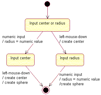
UML provides a means to describe and graphically represent state machines using statechart diagrams, that prove useful when designing dialog state commands. Let's take the example of the Line command [2]. The Line command, as any state dialog command, could be described as a state machine and represented using the UML notation [3] as shown in Fig. 1.
|
| Fig. 1: The Line Command Statechart Diagram |
The state machine progresses from the initial state to the final state. The dialog flow starts with the initial state, which is a pseudo state that has no incoming transition. The command is never in the initial state that automatically skips to the first state. This first state is dedicated to the start point input and is shown as a state vertex using a round corner box that displays the state name. A prompt linked to the first state can invite the end user to indicate this start point. The transition between the first state and the second state is triggered as soon as the end user indicates a valid point. This happens when the expected event is detected (the mouse left key is pressed), and when the guard condition is satisfied. The transition action, that is create a temporary point, is executed. A prompt linked to the second state can then invite the end user to indicate the end point. The transition to the final state is triggered as soon as the end user indicates a valid point. This creates the line. The final state is reached, and the command completes.
[Top]
We use the UML notation [3]
| State vertices | Round corner boxes showing the state name | |
| Transitions | Arrows between state vertices | |
| Initial state | A small solid filled circle | |
| Final state | A circle surrounding a small solid filled circle | |
| Events | Text | left-mouse-down |
| Guard conditions | Text between square brackets | [point indicated && point valid] |
| Actions | Text beginning with a slash | / create line |
[Top]
Command input can be a bit more complex than the one of the Line command shown above. A composite input can be necessary when an applicative task requires at least two input without taking care of the order in which they are provided by the user. This is a common situation as illustrated by a Sphere creation dialog:
With simple states, the statechart diagram could be as shown in Fig. 2.
 |
| Fig. 2: The Sphere Command Statechart Diagram with Simple States |
But composite input can be also described thanks to concurrent composite states. A composite state is the result of a state decomposed into substates. It is said to be concurrent if the decomposition results in substates that are all active, or non-concurrent if one only is active. Each substate can in turn be refined into its own substates.
Using a concurrent composite state, the sphere dialog statechart diagram is simplified, as shown in Fig. 3. It is made of a single concurrent composite state between the initiaml and the final states, that includes two concurrent substates. These two substates are active when the state machine transitions from the initial state to the concurrent composite state. Each substate is shown as a nested statechart diagram, including its own initial state, and its own final state. Both final states must have been reached to trigger the transition that creates the sphere.
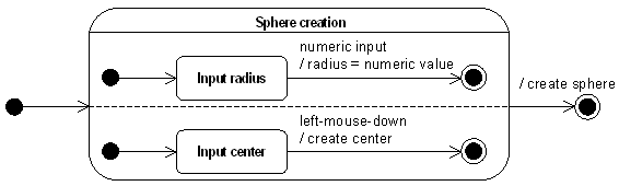 |
| Fig. 3: The Sphere Command Statechart Diagram with a Concurrent Composite State |
[Top]
A dialog agent translates a user interaction into a user input. This translation is managed by a state machine that is encapsulated by the dialog agent. As an example, the indication agent interprets a left button mouse click as a 2D-coordinate input.
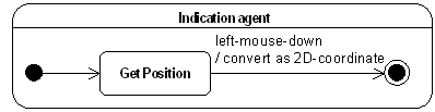
The dialog agent hides the details of how a user interaction, here a mouse click in a 2D viewer, is translated as a user input, that is 2D coordinates.
The keypoint is that dialog agents strenghtens the MVC model by shifting from an event-driven dialog to an input-driven dialog: using a indication agent allows a dialog command to read 2D coordinates without taking care of how the end user provides them, for example by keying numeric values or by clicking the left button of the mouse in a 2D viewer.
[Top]
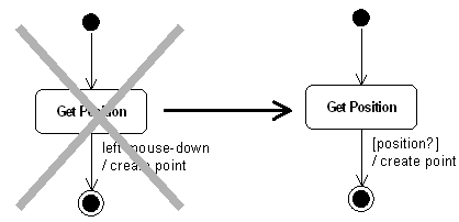
The new representation highlights event encapsulation by using input-driven transitions instead of event-driven transitions.
An input-driven transition is a kind of condition-driven transition which requires a user input. The condition has a validation responsibility toward the end user input: the input may be constrained. For example, the position should be within the drawing sheet ([position within sheet?]), or elsewhere ([position?]).
[Top]
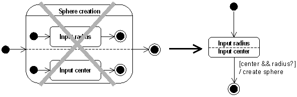
Using dialog agents simplifies further the Sphere dialog:
[Top]
Statechart diagrams representing state dialog commands are often input-driven. This characteristic impacts the test of conditions:
Some dialogs contain ambiguous conditions. In this case the transition order is crucial: the first transition which matches the user interaction wins while the others are not even warned.
[Top]
A state dialog command embodies a part of the developer's know-how to interact with the end user like an alter-ego. This section shows how this interactivity takes place.
From the user's point of view, the Line dialog follows a step by step scenario:
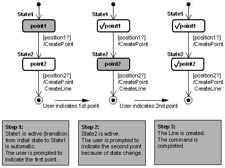
In the case of the Line command, the dialog agent to acquire points is recycled after the first transition to be reused in the second transition as if it were a new one.
[Top]
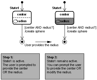
Once a valid input has been provided, the agent becomes inactive (this is shown by the checkmark): the user is no more prompted to provide an input.
Graphical Representation: ![]() The checkmark symbolizes a valid input.
The checkmark symbolizes a valid input.
The one-shot input behavior doesn't make a difference in the Line command dialog but it is not the case with the Sphere command dialog:

[Top]
A repeater agent is not deactivated by a user input as opposed to a one-shot agent (default mode). If we set the radius agent as a repeater in the Sphere dialog, the user will be able to modify the radius as long as the center is not provided.
Graphical Representation: ![]() The repeat mark symbolizes a repeater agent.
The repeat mark symbolizes a repeater agent.
The repeated input behavior for the radius input of the Sphere command dialog enables the end user to modify the radius value after it was input, as long as the center is not input.
[Top]
A state dialog command is modeled as a state machine and can be graphically represented using a statechart diagram expressed using the Unified Modeling Language (UML).
Dialog agents are specific encapsulated state machines that simplifies the dialog by replacing several states and event-driven transitions by a composite state and a simple input-driven transition. Dialog agents can be valued in one shot, or proposed again for input value mùodification. They can also be recycled.
[Top]
| [1] | Unified Modeling Language - UML Semantics version 1.1 |
| [2] | Getting Started with State Dialog Commands |
| [3] | Unified Modeling Language - UML Notation Guide version 1.1 |
| [Top] | |
| Version: 1 [Jan 2000] | Document created |
| [Top] | |
Copyright © 2000, Dassault Systèmes. All rights reserved.