Mechanical Design |
Drafting |
Creating a Distance Dimension on Interactive GeometryHow to create a distance dimension between two 2D lines |
| Use Case | ||
AbstractThis article discusses the CAADrwCreateDim.cpp use case. This use case explains how to edit a dimension dress-up. |
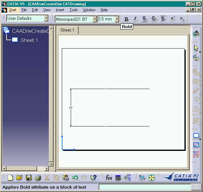
In this use case you will learn how to create an associative dimension on two 2D lines.
[Top]
CAADrwCreateDim is a use case of the CAADraftingInterfaces.edu framework that illustrates DraftingInterfaces framework capabilities.
[Top]
This sample creates a dimension on two 2D lines in batch mode:
|
|
[Top]
To launch CAADrwCreateDim, you will need to set up the build time environment, then compile CAADrwCreateDim along with its prerequisites, set up the run time environment, and then execute the use case [1].
When you launch the use case, pass the full pathname of the file into which you you want to store the created document as argument: for example Result.CATDrawing.
e:> CAADrwCreateDim Result.CATDrawing |
$ CAADrwCreateDim /u/users/Result.CATDrawing |
[Top]
The CAADrwCreateDim use case is made of one source file named CAADrwCreateDim.cpp located in the CAADrwCreateDim.m module of the CAADraftingInterfaces.edu framework:
| Windows | InstallRootDirectory\CAADraftingInterfaces.edu\CAADrwCreateDim.m\ |
| Unix | InstallRootDirectory/CAADraftingInterfaces.edu/CAADrwCreateDim.m/ |
where InstallRootDirectory is the directory where the CAA CD-ROM
is installed.
[Top]
There are six steps in CAADRWCreateDim:
[Top]
int main(int    iArgc,   // Number of arguments (1)
         char** iArgv)   // Path to the new *.CATDrawing document
{
   // Check arguments
   if(2 != iArgc) return 1;
   const char *pfileNameOut = iArgv[1];


   // CREATE THE SESSION
   // ==================

   CATSession *pSampleSession = NULL;
   HRESULT hr = ::Create_Session("SampleSession",pSampleSession);
   if (FAILED(hr)) return 1;


   // DRAWING DOCUMENT CREATION
   // =========================

   CATDocument* pDoc = NULL;
   hr = CATDocumentServices::New("CATDrawing", pDoc);
   if (FAILED(hr))
   {
      // Ends session
      ::Delete_Session("SampleSession");
      return 2;
   }
...
|
This section represents the usual sequence for creating a CATIA document.
[Top]
...
  // Gets the drawing feature using the CATIDftDocumentServices interface
   CATIDrawing *piDrawing = NULL;
   CATIDftDocumentServices *piDftDocServices = NULL;
   CATIContainer_var spDrwcont = NULL_var;
   CATISpecObject_var spSpecObj = NULL_var;
   if (SUCCEEDED(pDoc->QueryInterface(IID_CATIDftDocumentServices, (void **)&piDftDocServices)))
   {
      piDftDocServices->GetDrawing(IID_CATIDrawing, (void **)&piDrawing);
      piDftDocServices->Release();
      spSpecObj=piDrawing;
      spDrwcont = spSpecObj->GetFeatContainer();
   }
   else return 3;
...
|
The root feature of a drawing document is the Drawing that is the feature that implements the CATIDrawing interface. We can get a pointer to CATIDrawing using the CATIDftDocumentServices interface, which is implemented by the document. The GetDrawing method first argument is the interface you want to get on the drawing.
[Top]
...
  if (!!spDrwcont)
   {
      CATIDftStandardManager *piStdmgr = NULL;
      HRESULT rc = spDrwcont->QueryInterface(IID_CATIDftStandardManager,(void**)&piStdmgr);
      if (SUCCEEDED(rc))
      {
         //  Find a standard in the list of allowed standards (ie. the list of .CATDrwSTD files in the reffiles directory)
         CATIStringList *piListstd = NULL;
         if ( SUCCEEDED(piStdmgr->GetAvailableStandards(&piListstd)) )
         {
            wchar_t  *wstd = NULL;
            unsigned int  nbrstd;
            piListstd->Count(&nbrstd);
            CATUnicodeString stdname;
            const CATUnicodeString ANSI_UncS = "ANSI";
            for (unsigned int indice = 0; indice < nbrstd; indice ++)
            {
               if ( SUCCEEDED ( piListstd->Item ( indice, &wstd ) ) )
               {
                  stdname.BuildFromWChar(wstd);
 		  if ( stdname == ANSI_UncS )
		  {
                     // Import the ANSI standard in the document
                     piStdmgr->ImportStandard (wstd);
                     break;
                  }
               }
            }
            piListstd->Release();
            piListstd=NULL;

         }

         piStdmgr->Release ();
         piStdmgr=NULL;
      }
   }
...
|
The reffiles directory is accessible in runtime view.
[Top]
...
 // We are working in main view of the current sheet
   CATISheet_var spSheet = piDrawing->GetCurrentSheet();
   piDrawing->Release();
   CATIView_var spMainView = spSheet->GetMainView();


   // GEOMETRY CREATION
   // =================
   // We now can create geometries in the main view after :
   //   - Setting the view as the current one
   //   - Getting the view geometry factory interface
   spSheet->SetCurrentView(spMainView);
   CATI2DWFFactory_var spGeomFactory = spMainView;

   double X[2] = { 100.0, 200.0};
   double Z[2] ={ 50.0, 130.0};
   double startPoint[2], endPoint[2];

   // Creation of lines
   startPoint[0] = X[0];
   startPoint[1] = Z[0];
   endPoint[0] = X[1];
   endPoint[1] = Z[0];
   CATISpecObject_var spLine1 = spGeomFactory->CreateLine(startPoint, endPoint);

   startPoint[0] = X[0];
   startPoint[1] = Z[1];
   endPoint[0] = X[1];
   endPoint[1] = Z[1];
   CATISpecObject_var spLine2 = spGeomFactory->CreateLine(startPoint, endPoint);
...
|
To create geometric elements in a view, the view has to be current.
[Top]
...
   // Gets the view annotation factory
   CATIDrwAnnotationFactory_var spAnnFactory = spMainView;

   // Vertical distance dimension creation between Line1 and Line2
   CATDrwDimType dimType = DrwDimDistance;
   CATDimDefinition dimDef;
   CATIUnknownList * piSelectionsList =NULL;
   CATIUnknownListImpl * piListsel = new CATIUnknownListImpl();
   piListsel->QueryInterface(IID_CATIUnknownList, (void **) &piSelectionsList);
   piListsel->Release();
   piListsel=NULL;
   IUnknown * piLine1 = NULL;
   IUnknown * piLine2 = NULL;
   spLine1->QueryInterface(IID_IUnknown, (void **)&piLine1);
   spLine2->QueryInterface(IID_IUnknown, (void **)&piLine2);
   piSelectionsList->Add(0, piLine1);
   piSelectionsList->Add(1, piLine2);

   CATIDrwDimDimension * piDimHoriz = NULL;
   double pt1[2] = {10.0, 15.0};
   double  * pts[2];
   pts[0] = pt1;
   pts[1] = pt1+1;
   dimDef.Orientation = DrwDimAuto;
   hr = spAnnFactory->CreateDimension(piSelectionsList,pts,dimType,&dimDef,&piDimHoriz);

   if (piLine1) piLine1->Release();
   if (piLine2) piLine2->Release();
   if (piDimHoriz) piDimHoriz->Release();
   if (piSelectionsList) piSelectionsList->Release();
...
|
[Top]
...
  // Save the result
  CATDocumentServices::SaveAs(*pDoc, (char *)pfileNameOut);
   CATDocumentServices::Remove (*pDoc);
   //Ends session and drops document
   ::Delete_Session("SampleSession");

   return 0;
}
|
This section represents the usual sequence for saving a newly created CATIA document.
[Top]
This use case shows the objects and interfaces used when creating a dimension in a main view of a CATDrawing document. The Dimension is created using the CATIDrwAnnotationFactory interface.
[Top]
| [1] | Building and Lauching CAA V5 Samples |
| [2] | Creating a New Document |
| [Top] | |
| Version: 1 [Jan 2000] | Document created |
| [Top] | |
Copyright © 2000, Dassault Systèmes. All rights reserved.