Fig 1: The part document containing the Plane "PlaneForSection"
Mechanical Design |
Drafting |
Creating a Section View from a PlaneHow to create a section view with the cutting profile associative to a plane |
| Use Case | ||
AbstractThis article discusses the CAADrwCreateSectionFromPlane use case. This use case explains how to create a generative section view defined by a cutting profile associative to a plane. Thus if the plane is moved, the section view will modified after update. |
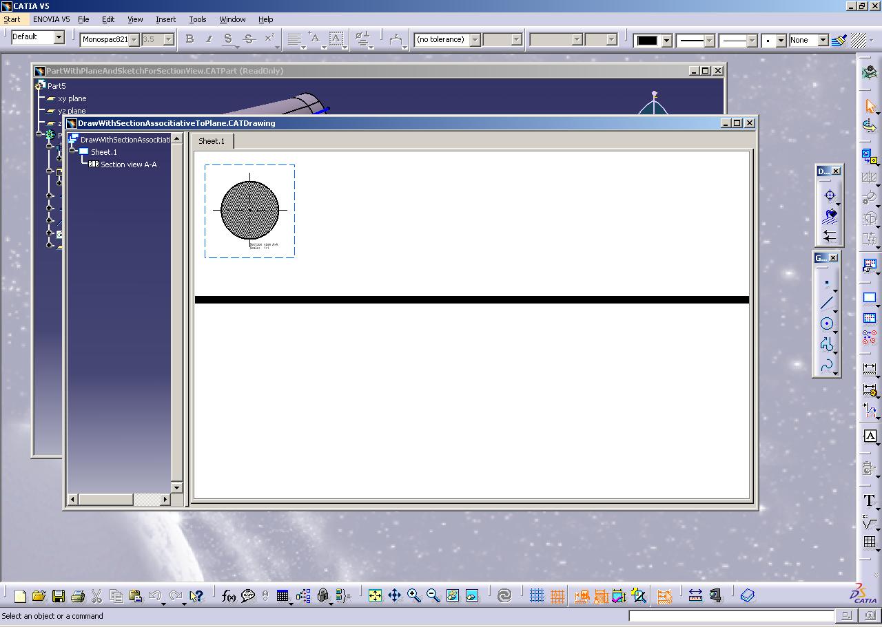
This use case is intended to show you how to create a Drawing generative section view from a 3D Plane.
|
Fig 1: The part document containing the Plane "PlaneForSection" |
|
|
The PlaneForSection Plane (yellow plane in the viewer) allows you to manage the cutting profile of the Drawing Section View from the 3D document.
[Top]
CAADrwCreateSectionFromPlane is a use case of the CAADraftingInterfaces.edu framework that illustrates DraftingInterfaces framework capabilities.
[Top]
|
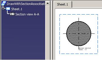
Fig. 2: Drawing Document with the new Section view |
 |
[Top]
To launch CAADrwCreateSectionFromPlane, you will need to set up the build time environment, then compile CAADrwCreateSectionFromPlane along with its prerequisites, set up the run time environment, and then execute the use case [1].
When you launch the use case, pass the full pathname of the Drawing file as argument. A Part file is delivery in the following path: CAADraftingInterfaces.edu\CNext\resources\graphic\PartWithPlaneAndSketchForSectionView.CATPart.
e:> mkrun -c cmd CAADrwCreateSectionFromPlane c:\...\PartWithPlaneAndSketchForSectionView.CATPart c:\DrawingTestOutput.CATDrawing |
$ mkrun -c cmd CAADrwCreateSectionFromPlane /u/users/.../PartWithPlaneAndSketchForSectionView.CATPart /u/users/DrawingTestOutput.CATDrawing |
[Top]
The CAADrwCreateSectionFromPlane use case is made of a single source file named CAADrwCreateSectionFromPlane.cpp located in the CAADrwCreateSectionFromPlane.m module of the CAADraftingInterfaces.edu framework:
| Windows |
InstallRootDirectory\CAADraftingInterfaces.edu\CAADrwCreateSectionFromPlane.m\ |
| Unix |
InstallRootDirectory/CAADraftingInterfaces.edu/CAADrwCreateSectionFromPlane.m/ |
where InstallRootDirectory is the directory where the CAA
CD-ROM is installed.
[Top]
There are five steps in CAADrwCreatViewFrom3D:
[Top]
int main(int iArgc, // Number of arguments (2)
char** iArgv) // Path to the new *.CATDrawing document
{
// Check arguments
if(3 != iArgc) return 1;
const char *pfileNamePart = iArgv[1];
const char *pfileNameOut = iArgv[2];
int code_err = 1;


// CREATE THE SESSION
// ==================
CATSession *pSampleSession = NULL;
HRESULT hr = ::Create_Session("SampleSession",pSampleSession);
if (FAILED(hr)) return 1;
... |
This section represents the usual sequence for loading a CATIA document [2].
[Top]
...
   // DRAWING DOCUMENT CREATION
   // ===============================
   CATDocument* pNewDoc = NULL;
   CATDocumentServices::New("CATDrawing", pNewDoc);
...
|
The other steps to fully initialize the drawing document are included in the specific sub program, CreateViewFrom3DInDrawingDoc.
[Top]
...
// READ THE PART DOCUMENT AND GET THE APPROPRIATE SKETCH
// =============================================================
CATDocument *pDocPart = NULL;
if( SUCCEEDED(CATDocumentServices::OpenDocument(pfileNamePart, pDocPart)) && pDocPart)
{
  CATInit_var spInitOnDoc(pDocPart);
  if(NULL_var != spInitOnDoc)
  {
    // Retrieves the root container
    CATIPrtContainer * piPrtCont = (CATIPrtContainer*) spInitOnDoc->GetRootContainer("CATIPrtContainer");
    if (piPrtCont)
    {
      // Get the part feature of the container.
      CATIPrtPart_var spPart = piPrtCont->GetPart();

      // Get the appropriate plane
      CATIDescendants *piDescPart=NULL;
      if (SUCCEEDED(spPart->QueryInterface(IID_CATIDescendants,(void**)&piDescPart)))
      {
        CATListValCATISpecObject_var listFeatures;

        piDescPart->GetAllChildren ("CATPlane",listFeatures) ;

        int nbChilds = listFeatures.Size();
        CATISpecObject_var spFeat;
        for (int i = 1; i <= nbChilds; i++)
        {
          spFeat = listFeatures[i];
          if (NULL_var != spFeat)
          {
            CATPlane* piPlane = NULL;
            if (SUCCEEDED(spFeat->QueryInterface(IID_CATPlane, (void**)&piPlane)))
            {
              CATIAlias *piPlaneAlias = NULL;
              if (SUCCEEDED(piPlane->QueryInterface(IID_CATIAlias, (void**)&piPlaneAlias)))
              {
                CATUnicodeString PlaneName = piPlaneAlias->GetAlias();
	        const CATUnicodeString PlaneSection_UC = "PlaneForSection";
                if (PlaneName == PlaneSection_UC)
                  hr = CreateSectionViewFromPlanInDrawingDoc(pNewDoc, piPlane);

...
|
All the planes in the Part document are retrieved by using the
GetAllChildren method of the CATIDescendants interface. The
appropriate plane is extracted from the list thanks to the GetAlias
method of the CATIAlias interface.
[Top]
... // -------------------------------------------------------------------------------------------------------------------------------------------------------
// Sub program to create an associative section view from Plane.
// -------------------------------------------------------------------------------------------------------------------------------------------------------
HRESULT CreateSectionViewFromPlanInDrawingDoc(CATDocument *ipNewDoc, CATPlane*ipiPlane)
{
HRESULT hr = E_FAIL;
if (ipNewDoc && ipiPlane)
{
// DRAWING STANDARD CREATION
// ===============================
// Gets the drawing feature using the CATIDftDocumentServices interface
CATIDftDrawing *piDftDrawing = NULL;
CATIDftDocumentServices *piDftDocServices = NULL;
CATIContainer_var spDrwCont;
if (SUCCEEDED(ipNewDoc->QueryInterface(IID_CATIDftDocumentServices, (void **)&piDftDocServices)))
{
piDftDocServices->GetDrawing(IID_CATIDftDrawing, (void **)&piDftDrawing);
piDftDocServices->Release();
piDftDocServices = NULL;
if (piDftDrawing)
{
CATISpecObject *piDrawingSO=NULL;
if (SUCCEEDED(piDftDrawing->QueryInterface(IID_CATISpecObject,(void **)&piDrawingSO)))
{
spDrwCont = piDrawingSO->GetFeatContainer();
if (NULL_var != spDrwCont)
{
CATIDftStandardManager *piStdmgr = NULL;
hr = spDrwCont->QueryInterface(IID_CATIDftStandardManager,(void**)&piStdmgr);
if (SUCCEEDED(hr))
{
// Find a standard in the list of allowed standards (ie. the list of .CATDrwSTD files in the reffiles directory)
CATIStringList *piListstd = NULL;
if ( SUCCEEDED(piStdmgr->GetAvailableStandards(&piListstd)) && piListstd )
{
unsigned int nbrstd = 0;
piListstd->Count(&nbrstd);
for (unsigned int indice = 0; indice < nbrstd; indice ++)
{
wchar_t *wstd = NULL;
if ( SUCCEEDED ( piListstd->Item ( indice, &wstd ) ) && wstd )
{
CATUnicodeString stdname;
const CATUnicodeString ISO_UncS = "ISO";
stdname.BuildFromWChar(wstd);
if ( stdname == ISO_UncS )
{
// Import the ISO standard in the document
piStdmgr->ImportStandard (wstd);
break;
}
delete[] wstd; wstd = NULL;
}
}
piListstd->Release(); piListstd=NULL;
}
piStdmgr->Release (); piStdmgr=NULL;
}
}
// Creation of new generative seection view from 3D Sketch in the active sheet of the Drawing Document
CATIDftView *piDftSectionViewFrom3D = NULL;
CATIDftSheet *piDftSheet = NULL;
piDftDrawing->GetActiveSheet(&piDftSheet);
// View anchor point definition
double ptOrigin[2] = {150.0,150.0};
CATMathVector normalSketch;
CATI2DLine_var spFirstLine;
CATIDftGenViewFactory *piDftGenViewFact = NULL;
if (piDftSheet && SUCCEEDED(piDftSheet->QueryInterface(IID_CATIDftGenViewFactory,(void **)&piDftGenViewFact)))
{
// vecPro argument compute:
// VecPro must be a direction perpandicular to the direction of the cutting profile defined by two extremities points and included in the plane.
CATIGeometricalElement *piGeomElem = NULL;
if (SUCCEEDED(ipiPlane->QueryInterface(CATIGeometricalElement::ClassId(), (void**) &piGeomElem)))
{
CATCell_var spCell;
CATBody_var spBody;
spBody = piGeomElem->GetBodyResult();
spCell = piGeomElem->GetGeometryResult();
if (NULL_var == spCell && NULL_var != spBody)
{
CATLISTP(CATCell) AllFaces;
spBody->GetAllCells(AllFaces, 2);
int FaceCount = AllFaces.Size();
for (int i = 1 ; i <= FaceCount; i++)
{
if (AllFaces[i])
{
spCell = CATCell_var(AllFaces[i]);
break;
}
}
}
CATMathPlane mathPlane;
ipiPlane->GetAxis(mathPlane);
CATMathPoint iLimitPoints[2];
              double Pt1Coord[2] = {-100.0,0.0};
              double Pt2Coord[2] = {100.0,0.0};
              mathPlane.EvalPoint(Pt1Coord[0],Pt1Coord[1],iLimitPoints[0]);
              mathPlane.EvalPoint(Pt2Coord[0],Pt2Coord[1],iLimitPoints[1]);
              CATMathVector vecProfile = iLimitPoints[1] - iLimitPoints[0];
              CATMathVector vecNormalToPlane;
              mathPlane.GetNormal (vecNormalToPlane);
              CATMathVector ProVec = vecNormalToPlane^vecProfile;
              CATMathDirection vecPro;
              vecPro.SetCoord(ProVec.GetX(),ProVec.GetY(),ProVec.GetZ());

              // Offset
              int viewProfile = 0;

              // Section View defined by a plane
              CATISketch *ipi3DSketch = NULL;

              // Plane defined in Part Document
              CATIProduct *piProduct= NULL;
              hr = piDftGenViewFact->CreateStandAloneSectionView(ptOrigin, DftSectionView, vecPro,viewProfile, ipi3DSketch,spCell,spBody,iLimitPoints, piProduct,
 &piDftSectionViewFrom3D);
              piGeomElem->Release();piGeomElem=NULL;
            }
            piDftGenViewFact->Release();piDftGenViewFact=NULL;
          }

          piDrawingSO->Release();
          piDrawingSO=NULL;
        }
        piDftDrawing->Release();
        piDftDrawing = NULL;
      }
    }
  }
  return hr;
}
...
|
The sub program CreateSectionViewFromPlaneInDrawingDoc create a
Section View from a Plane by using the method CreateStandAloneSectionView
of the CATIDftGenViewFactory interface. This interface is
implemented by the Sheet. the Drawing Standard has to be initialized before the
Drawing View creation.
Main arguments to initialize are:
ptOrigin: Anchor point of the section viewDftSectionView: Type of the SectionVecPro: VecPro must be a direction
perpandicular to the direction of the cutting profile defined by two
extremities points and included in the plane.Vecpro orientation informs the system which part will be
drawn in the section view.spCell and spBody characterize the plane in the
Part document.iLimitPoints: the coordinates of 3D points to define the
limits of the profile.The other arguments are useless in this sample.
[Top]
...
// SAVE THE RESULT
// =================
if (pNewDoc)
{
  CATDocumentServices::SaveAs(*pNewDoc, (char *)pfileNameOut);
  CATDocumentServices::Remove (*pNewDoc);
}

//ENDS SESSION AND DROPS DOCUMENT
//=====================================
if (pDocPart)
  CATDocumentServices::Remove (*pDocPart);

::Delete_Session("SampleSession");
|
This section represents the usual sequence for saving a newly created CATIA document.
[Top]
This use case shows the way to :
CreateStandAloneSectionView method of the CATIDftGenViewFactory[Top]
| [1] | Building and Launching a CAA Use Case |
| [2] | Loading a Document |
| [Top] | |
| Version: 1 [Jan 2005] | Document created |
| [Top] | |
Copyright © 2005, Dassault Systèmes. All rights reserved.