Silhouette functionality:
- allows to select a part or an assembly and only keeps the external
facets of the selection. When in interaction with other parts, the same
accuracy is kept while the file size is significantly reduced. For
reviewing, the outer aspect of the part is identical to the original
model (surface appearance, color...)
- lets you work on the Accuracy parameter in
order to optimize the number of removed facets inside the silhouette
- allows you to work with 1 to 6 standard views and to use a camera from DMU Navigator to create an additional view of the silhouette. You can easily keep track of details that might have been lost with the standard views: for example you can set a camera on a hole axis in order to visualize data hidden from most views.
- you can select the reference axis system along which the computation will be done
For more detailed information, refer to More About Silhouette Functionality
You might find useful to manage automatically your Silhouette result as an alternate shape of the initial component and specify a directory/path to save your result (see Customizing DMU Optimizer Settings)
Note: If your are not working in alternate shape mode, it is strongly recommended to use the Reference Product option to avoid positioning problems when reinserting products. Please read About Reference Product
-
Click the Silhouette icon
 from the DMU Optimizer toolbar.
The Silhouette dialog box appears: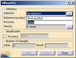
-
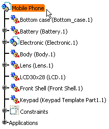
Select the product you need to simplify (i.e. Mobile phone) in the specification tree or in the geometry area.
Click the More button:
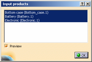
The Input Products dialog box is displayed
The listed selection corresponds to the products you selected before you launched a calculation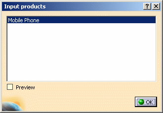
While the Input Products dialog box is active, you can change the selection in your session: the listed selection will be accordingly modified, for example: 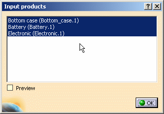
Likewise, if you change the selection in the Input products dialog box, the selection in your session will be correspondingly modified. You can select the Preview check box to see a preview of you product selection, for example:
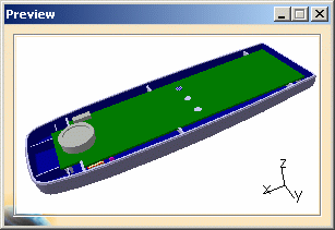

Note: neither the Input Products dialog box nor the Preview check box are available when working in alternate shape mode. 
You can select any node within the specification tree (terminal/non terminal) and even multi-select them provided that you are not working in alternate shape mode. -
Enter the desired value in the Accuracy field for instance 2mm.
Please refer to More About Silhouette Functionality-Step 1
Setting the Accuracy:
Specify the silhouette calculation accuracy. A lower value results in a slower computation time, but a lighter silhouette representation. -
Click the View(s) button
 to display the selection list. Refer to
More About Silhouette
Functionality-Step 2
 -
Select the desired views. The 6 views for instance.
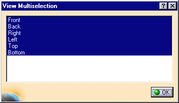
-
Click OK to confirm your operation.
-
Click Preview to launch the calculation
The progress bar is displayed letting you monitor and, if necessary, interrupt (Cancel option) the calculation. 
The Preview window is also displayed. 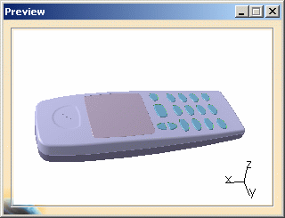
The number of triangles representing the silhouette result is displayed in the Number of triangles field as shown below: 

You can simplify your silhouette result within the Silhouette dialog box. For more detailed information, please read Using Simplification Command and More About Simplification -
Select the Accuracy check box in the Simplification area.
-
Enter a new value if needed.
In our example enter 0.2mm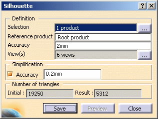

The number of triangles representing the simplified result is displayed in the Number of triangles area.
If you are not satisfied, click once in the accuracy field, enter a new value, press Enter and then click Preview. -
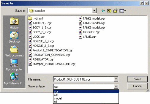
Click Save. The Save As dialog box is displayed:
- Set the Type to .cgr. You can also save your resulting shape in .wrl, .model .stl formats
- Identify the folder in which you want to save the file
- Enter a file name
-
Click Save
Alternate Shape:
(Optional)
You can manage automatically your Silhouette result as an alternate
shape of the initial component.
For this:
- Select Tools > Options from the menu bar.
The Options dialog box appears. - Expand the Digital Mockup category from the upper-left tree.
- Select DMU Optimizer item to display the
corresponding tab.
The Alternate Shapes Management is available: - Select the Silhouette check box: the option
"Activate" is automatically selected.

The silhouette result is going to be added to the initial component as a new representation.
For more details, please refer to Customizing DMU Optimizer Settings and Managing as an Alternate Shape.
![]()