About Reference Product
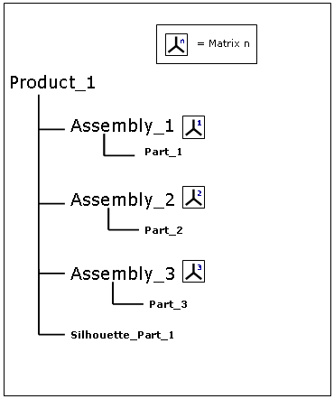
Before R11 level, when you were not working in alternate shape mode and after having saved a silhouette representation from a sub-assembly, you could only reinsert it into the root product (using Insert->Existing Component...) It means you could not reinsert any representation into a sub-assembly at any level. Thus, there was no update in positioning the silhouette representation with the product. See figure 1 below:
(before R11)
-
You create a silhouette of Part_1.
-
The silhouette of Part_1 is calculated with respect to Product1 absolute axis system.
-
Therefore, you can only reinsert your result into Product1.
(from R11)
-
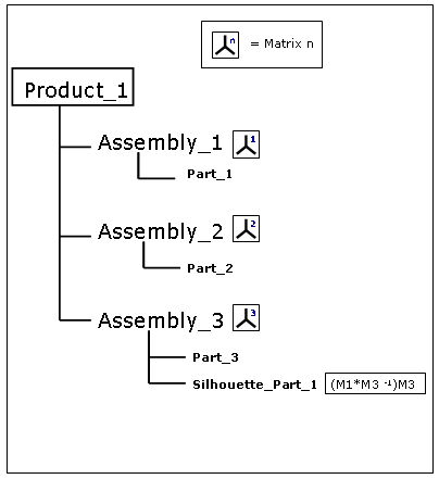
You create a silhouette of Part_1 and you want to reinsert it into Assembly_3
(Selection = Part_1, Reference Product = Assembly_3) -
The silhouette of Part_1 is calculated with respect to Assembly_3 axis system.
-
You can reinsert your silhouette result into Assembly_3 (reference product)
Note in other scenarios, you might find useful to manage automatically your Silhouette result as an alternate shape of the initial component and specify a directory/path to save your result (see Customizing DMU Optimizer Settings)
-
Select Product2 in the specification tree

-
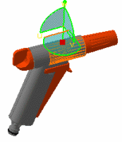
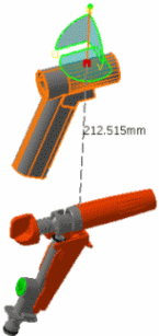
Move your product with the 3D compass using the drag and drop capability
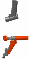
-
Select REGULATION_COMMAND (REGULATION_COMMAND.1) in the specification tree.
-
Click the Silhouette icon
 from the DMU Optimizer toolbar.
The Silhouette dialog box appears: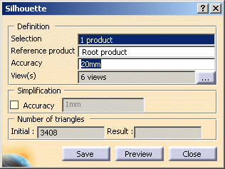
-
Select a reference product of your choice (in our example, select Product2.1 in the specification tree)
-
Enter the desired value in the Accuracy field for instance 2mm.
Refer to More About Silhouette Functionality-Step 1
Setting the Accuracy:
Specify the silhouette calculation accuracy. A lower value results in a slower computation time, but a "lighter" silhouette representation. -
Click the Preview button
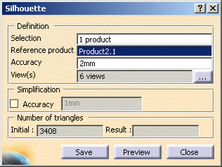
-
Click Save. The Save As dialog box is displayed:
- Set the Type to .cgr. You can also save your resulting shape in .wrl, .model .stl formats
- Identify the folder in which you want to save the file
- Enter a file name
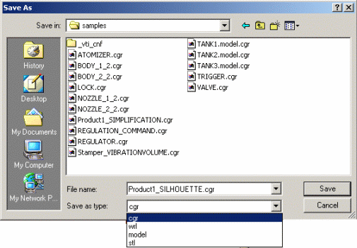
-
Click Save
Now, insert your silhouette result into your product -
Right-click Product2 in the specification tree.
-
Select Components-> Existing component from the contextual menu displayed. Select the silhouette.cgr document you have just saved.
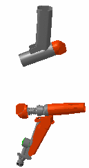
This is what you obtain: 
![]()