3D PLM Enterprise Architecture |
3D Visualization |
Graphical PropertiesHow to use or implement the CATIVisProperties Interface |
| Technical Article | ||
AbstractThe first objective of this article is to understand what are the graphical properties. The second is to explain how they are integrated in the visualization process. Three interfaces are important: CATIVisProperties, CATIVisu and CATIProperty. The first enables to associate with a feature a set of graphical properties, the second uses the CATIVisProperties interface to update the graphic attributes of the graphic representations, and the last stores the data. CATIVisProperties is the main interface of this system.
|
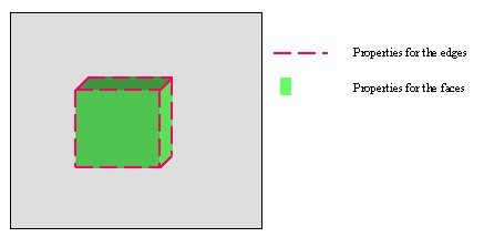
Before to go into all the details, a little example to set the subject. Suppose a cube feature [Fig.1 ] which is composed of two types of geometry: faces (6) and edges (12). On this feature, for the set of faces and for the set of edges, graphical properties are put. For faces, it is possible to set a color, a degree of opacity and for the lines, a color, a type and a thickness.
|
The principe of the graphical properties lies on the fact that an element (a feature) contains one or several sub-types. A sub-type is sorted by type of geometry: point, line, surfacic etc.... and for each sub-type a set of graphical properties is associated. To integrate them in the visualization process, there is three main interfaces: CATIVisProperties, CATIProperty et CATIVisu.
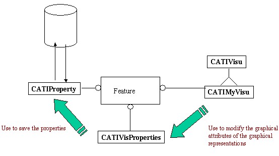 |
On this shema, you can see that:
You can notice that if the componant is not a feature, it can't have graphical properties because the CATIProperty is to use AsIs.
The graphical properties are visual properties, it means that the properties can be directly use by the visualization processus. These attributs, classified by storage way, are the following:
The "Using Graphic Attributes" [1] article enables to familiarize you with this class.
The marker of the point is set at the CAT3DMarkeGP or CAT2DMarkerGP construction class.
The number of the layer .
To specify the type of the graphical properties, there is the CATVisPropertyType enum.
CATVPColor for the color CATVPOpacite for the opacityCATVPWidth for the line width (thickness)CATVPLineType for the line typeCATVPSymbol for the symbol of the markerCATVPShow for the show/no show flagCATVPPick for the pick/no pick flag CATVPInheritance for the inheritance flagCATVPLowInt for the lowint color flagCATVPLayer for the layerAt these values, an another one which doesn't represent a property but a set
of properties: CATVPAllProperties.
The data for the graphical properties (the color, the flag) will be write (read) on a CATVisPropertiesValues. It's detailed in the "Using CATIVisProperties" section.
The information stored on the CATIVisProperties is the type (s) of geometry supported by the feature.
CATIA V5 supplies some types of geometry, those in relationship with the dimension of the sub-type are:
CATVPPoint (O D)CATVPLine for a wire and CATVPEdge for a
line on a surface (1D)CATVPMesh for a surface (2D)an another is for the assembling models:
CATVPAsm At these five values, there is a last CATVPGlobalType. This type
regroups together the graphical properties independant of the sub-types: the
visibility state, the selectionnability state, the lowint color flag and the
number of the layer. Actually in fact, it is not possible to set the points of a
wire on a layer, and set its curves on an other layer. It is the globally the
element which is on a layer.
These six types, CATVPPoint, CATVPLine ,CATVPEdge
,CATVPMesh, CATVPAsm and CATVPGlobalType are
CATVisGeomType
To associate graphical properties for a type of geometry, there is the CATVisPropertiesValues class. On an instance of this class, you set the color, the type of point and so on.
On the CATIProperty interface, a copy of this instance is stored. So, a priori, you can set any graphical properties for any type of geometry. But at last, only the graphic properties interpretable by the process visualization are important. It means that you can set a degree of opacity for your lineic feature, but the visualization process could not translate that. The next section describes that.
In the visualization process, there are two cases to distinguish, even though they join together at the end. The total and the partial revisualization of the model. But at first, it is important to give the methods of the CATExtIVisu adapter class of the CATIVisu interface in relationship with the properties:
virtual CATRep * BuildRep()virtual void SetGraphicAttribut()virtual int ModifyRep(const CATNotification & iNotif)virtual void SetPointGraphicAttribute(CATRep * iRep,
CATVisPropertyType iPropertyType, CATVisPropertiesValues &
iPropertyValues)virtual void SetMeshGraphicAttribute(CATRep * iRep,
CATVisPropertyType iPropertyType, CATVisPropertiesValues &
iPropertyValues)virtual void SetLineGraphicAttribute(CATRep * iRep,
CATVisPropertyType iPropertyType, CATVisPropertiesValues &
iPropertyValuesvirtual void SetEdgeGraphicAttribute(CATRep * iRep,
CATVisPropertyType iPropertyType, CATVisPropertiesValues &
iPropertyValues)virtual void SetAsmGraphicAttribute(CATRep * iRep,
CATVisPropertyType iPropertyType, CATVisPropertiesValues &
iPropertyValues)After the construction of the graphic representation (CATRep class),
realized by the BuildRep method, the SetGraphicAttribut method
is called. The default implementation of this method, those of the CATExtIVisu
adapter class, calls successively (*) the following methods:
CATVPGlobalType)CATVPPoint)CATVPLine)CATVPMesh)CATVPEdge)CATVPAsm)(*) These methods are called only if the type of geometry, set in bracket in the previous list, is defined by the feature.
The SetGraphicAttribut method calls these methods with CATVPAllProperties
as second argument. It means that all the graphical properties are set
on the graphic representation for the given type of geometry.
After a CATModifyVisProperties notification, a partial
revisualization of the model is done. In fact only the graphical properties
are changed. This notification contains the type of the geometry and its new
graphical properties. The ModifyRep analyzes the input's
notification, and calls one of the six methods concerned by the type of
geometry. The difference between the total revisualization is the second
argument of these methods: it is not necessary CATVPAllProperties, but
can be one of the CATVisPropertyType enumeration as CATVPColor
for example.
In the two cases, the process converges towards the same methods. Their goal
is to modify the graphic representation (and their associated graphic
attributes) in taken account of the graphic properties set on the CATVisPropertiesValues
instance, the third argument of these methods. It is
important to know what do they do in their default implementation, because if
the default behavior doesn't fit your need, you will do reimplement those
concerned by the type of geometry defined by your feature. See "Implementing
CATIVisProperties".
Before to detail them, we have described the second and the third argument of
these six methods, there is still the first. It is a CATRep pointer
which comes from the visualization process. Indeed, it is the graphic
representation created in your BuildRep extension.
The graphical properties processed are the color and the symbol of the marker. The method takes care only the CAT3DPointRep or the CAT2DPointRep class. If your graphic representation is a CAT3DCustomRep, it will be necessary to reimplement it.
See SetEdgeGraphicAttribute
The graphical properties processed are the color and the degree of opacity. If the graphic representation is a CATSurfacicRep, the graphic attributes of each faces will be modified, and also the graphic attributes associated to each level of detail [2]. Otherwise, the graphic attribute of the graphic representation is changed.
The graphical properties processed are the color, the type and the thickness of the line. If the graphic representation is:
The graphical properties processed are the color, the type of the line, the thickness, the degree of opacity and the inheritance.
This section describes in table form [Tab.1] for each type of geometry, the graphical properties taken account by the CATExtIVisu methods that we have detailed just above.
|
In implementing the CATIVisProperties interface on your feature, you benefit automatically of the CATIAVisPropertySet automation interface .
If your feature implements CATIVisProperties, when you launch the Properties Commands, the Graphic tab page appears. Its contents depends on the type of geometry defined by the feature. There are three possible cases:
CATVPPoint
and/or CATVPLine and/or CATVPEdge and/or CATVPMesh
(with or without CATVPGlobalType):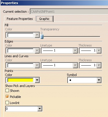 |
This is a sample with a feature which are the types CATVPGlobalType
and CATVPPoint. This page contains two frames:
CATVPPoint,
      CATVPLine, CATVPEdge
or CATVPMesh. If the type is not
supported by the feature, its options are disable. In this example, only
the point properties (color and symbol) are available. CATVPGlobalType type is supported by the
feature. CATVPAsm
(with or without CATVPGlobalType):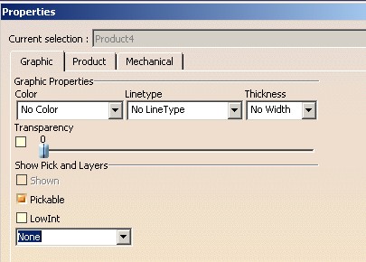 |
This is an example where the feature defined the types CATVPAsm and
CATVPGlobalType. This page contains two frames:
CATVPGlobalType
type is supported by the feature. CATVPGlobalType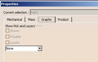 |
Only the "Show Pick and Layers" appears.
The Graphic Properties toolbar, [Fig. 6] is the following:
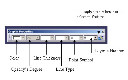 |
When a feature is selected, the toolbar is updated in taken account of the feature's properties. If several features are selected, the behavior is the following:
You can notice that in this toolbar, there is only one combo for each type of
property. Assume that your feature defined the CATVPPoint and the CATVPLine
types. These two types have in common the color property. So a choice must be
done to define the type concerned by the color property. It is the goal of the GetSubTypefromPath
method of the CATIVisProperties interface. This point will be
detailed in the Implementing
CATIVisProperties" section.
The Hide/Show command enables to hide or show the selected features. But to benefit of this functionality on your feature, it must implement the CATISelectShow interface. It uses the CATIVisProperties to modify the visibility state of the feature.
[Top]
If this section detailed the usage of the CATIVisProperties interface, the "Modifying Object Graphical Properties" article [3] exposes a concrete use case.
This interface contains five main methods:
GetPropertiesAtt(CATVisPropertiesValues & oValues,
    CATVisPropertyType iPropType, CATVisGeomType iGeomType )
SetPropertiesAtt(CATVisPropertiesValues &
iValues, CATVisPropertyType iPropType, CATVisGeomType iGeomType )
The first retrieves the properties from the CATIProperty interface and the second modifies them on the CATIProperty interface
These two methods function on the same principle: the property values are on the CATVisPropertiesValues instance and two keys
iGeomType, precises the type of the geometry
concerned by the property
iPropType, precises the type of the property
valid on the CATVisPropertiesValues instance Example: Lets change the color (CATVPColor for the property
type) of a line (CATVPLine for the geometry type)
represented by the pLine pointer.
... CATIVisProperties * pIVisPropertiesOnLine = NULL; HRESULT rc = |
At first, the CATVisPropertiesValues instance, MyPropertyOnLine,
is valuated with the color thanks to the SetColor method. Next
calling the SetPropertiesAtt method modifies on the CATIProperty
interface only the color of the line geometry because the second argument is
CATVPColor and the third is CATVPLine.
ResetPropertiesAtt(CATVisPropertyType iPropType,
CATVisGeomType iGeomType )
This methods enables to invalidate the property set on the CATIProperty.
It means that at the next GetPropertiesAtt calls, the
returned properties values will be the standard values. The returned code of
the GetPropertiesAtt method, S_AUTOMATIC, precises that the
returned properties values is the standard. To set new specific properties,
a new SetPropertiesAtt will be necessary.
Example: Always with the line, pointed by pIVisPropertiesOnLine,
the color of the CATVPLine geometry type is reseted.
... HRESULT rc = pIVisPropertiesOnLine ->ResetPropertiesAtt( |
In this example, you can see that after the ResetPropertiesAtt call,
for the same key CATVPColor and CATVPLine,
the GetPropertiesAtt method returns the S_AUTOMATIC
value. It means that the color sets on the MyPropertyOnLine
instance, is the standard color, so the same value as those returned by the GetStandardProperties
method with the same keys.
Note: if any SetPropertiesAtt call has been done on
the feature, it has standard values.
GetStandardProperties(CATVisPropertiesValues & oValues,
CATVisPropertyType iPropType,
    CATVisGeomType iGeomType )
This method retrieves the standard properties. These values are the values managed by the CATIVisProperties implementation [Tab. 2] and are not the standard of creation that you can manage with the "Standards..." command.
|
Caution: The contents of this table can be different between two
implementations of the CATIVisProperties interface. The DS features,
implementing the GetStandardProperties methods, have
perhaps another standard values. Here the standard values defined by the CATExtIVisProperties
methods are exposed.
IsGeomTypeDefined(CATVisGeomType iGeomType)Tells if a given type of geometry is recognized by the feature.
[Top]
If this section detailed the implementation of the CATIVisProperties interface, the "Implementing CATIVisProperties" article exposes a concrete use case. You will find this article in the Product Process Resouce (PPR) part of the CAA encyclopedie.
To implement this interface you use the CATExtVisProperties adapter class. There are two methods to overwrite:
IsGeomTypeDefinedIt is the method to define one or several type of geometry for the feature.
Here is an example for a feature which defined the CATVPPoint and
the CATVPGlobalType types.
...
HRESULT CAAEPstVisPropertiesPoint::IsGeomTypeDefined(CATVisGeomType & iGeomType)
{
    HRESULT rc = E_FAIL ;

    if ( (CATVPPoint == iGeomType) || (CATVPGlobalType == iGeomType) )
        rc =  S_OK ;
    return rc ;
}
...
|
This method returns S_OK when the type is valid otherwise E_FAIL.
Overwrite or not the methods of the CATExtIVisu adapter class of the CATIVisu interface
You have chosen one or several types among the following types: CATVPPoint,
CATVPLine, CATVPEdge, CATVPAsm, CATVPMesh.
But in studying the default behavior of the methods of the CATExtIVisu
class, associated at each type you have chosen, you note that their process
don't fit your need: the graphic representation of your feature will not be
correctly modified.
Take an example, the feature is a wire which contains lineic sub-elements
(lines) and points. The type of geometry are CATVPPoint and CATVPLine.
So the methods of the CATExtIVisu are SetPointGraphicAttribute
to modify the points attributes and SetLineGraphicAttribute for those
of the lines. The graphic representation of the feature is a CAT3DCustomRep
with one CAT3DMarkerGP for all the points and one CAT3DLineGP
for all the lines. It is necessary to overwrite these two methods because:
SetPointGraphicAttribute method doesn't process the CAT3DCustomRep
as graphic representation.SetLineGraphicAttribute method modifies all its graphic
attributes, so the attribute for the point will be also changed.GetSubTypeFromPathThis method enables to define the type of geometry concerned by the graphic properties displayed in the Graphic Properties toolbar. See the section "The Graphic Properties Toolbar"
Here an example for the point feature:
...
HRESULT CAAEPstVisPropertiesPoint::GetSubTypeFromPath(CATPathElement & iPathElement,
                                                      CATVisPropertyType iPropertyType,
                                                      CATVisGeomType & oGeomType,
                                                      unsigned int & oPropertyNumber)
    HRESULT rc = E_FAIL ;

    switch ( iPropertyType )
    {
    case CATVPColor:
    case CATVPSymbol:
        oGeomType = CATVPPoint ;

        rc = S_OK ;
        break;
    }
    oPropertyNumber = 0 ;
    return rc ;
}
...
|
In the toolbar, the color and the symbol are associated to the CATVPPoint
geometry.
You can note that oPropertyNumber should be always set to zero
and that the graphic properties associated to the CATVPGlobalType
type are not processed (CATVPShow, CATVPLayer, CATVPPick,CATVPLowint),
it is by default done.
[Top]
This article describes how the graphic properties are integrated in the visualization process. The principle is that a feature can have a set of graphic properties for each of its component's geometry. Each component is defined as a geometry type. Three interface are essentials:
It stores permanently the data. A feature natively implements this interface.
It kepts the type of geometry defined on the feature. Its implementation asks sometimes to overwrite some methods of the CATExtIVisu class adapter of the CATIVisu interface.
It uses the CATIVisProperties to know the properties to associate to the graphic representation.
[Top]
| [1] | Using Graphic Attributes |
| [2] | Creating Levels of Details |
| [3] | Modifying Object Graphical Properties |
| [Top] | |
| Version: 1 [Jun 2002] | Document created |
| [Top] | |
Copyright © 2002, Dassault Systèmes. All rights reserved.