3D PLM Enterprise Architecture |
3D Visualization |
Using Graphic AttributesSetting colors, linetypes, and thicknesses to representations, and understanding graphic attribute inheritance |
| Use Case | ||
AbstractThis article discusses the CAAVisRep use case. This use case explains how to use graphic attributes. |
This use case is intended to show how to set graphic attributes to graphic representations, how to manage graphic attribute inheritance, and describes some of these attributes.
[Top]
CAAVisRep is a use case of the CAAVisualization.edu framework that illustrates Vizualization framework capabilities.
[Top]
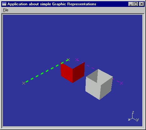
CAAVisRep creates two line representations, and two cuboid representations, and sets graphic attributes to these representations to display them as shown in Fig. 1.
|
[Top]
To launch CAAVisRep, you will need to set up the build time environment, then compile CAAVisRep along with its prerequisites, set up the run time environment, and then execute the use case [1].
[Top]
The CAAVisRep use case is made of two classes named CAAVisRepApplication and CAAVisRepWindow located in the CAAVisRep code is located in the CAAVisRep.m use case module of the CAAVisualization.edu framework:
| Windows | InstallRootDirectory\CAAVisualization.edu\CAAVisRep.m |
| Unix | InstallRootDirectory/CAAVisualization.edu/CAAVisRep.m |
where InstallRootDirectory is the root directory of your CAA V5
installation.
[Top]
To manage graphic attributes, there are four main steps:
[Top]
The 3D navigation viewer is an instance of the CATNavigation3DViewer
class. It is created in the CreateViewer method of the CAAVisBaseView
class that is called when the application is launched.
void CAAVisRepWindow::CreateViewer()
{
  _p3DViewer = new CATNavigation3DViewer(this,
                                         "Navigation3DId",
                                         CATDlgFraNoTitle,
                                         800, 450);
  _p3DViewer->SetBackgroundColor(0.2f,0.2f,0.6f);
  Attach4Sides( _p3DViewer);
}
|
The _pViewer pointer to the 3D navigation viewer is kept as a
data member of the CAAVisBaseView class. Its parameter are:
this |
The viewer parent in the dialog containment tree structure and in the command tree structure [a] |
Navigation3DId |
The viewer identifier |
CATDlgFraNoTitle |
The viewer has no title [b] |
850, 450 |
The viewer width and height expressed in pixels |
The SetBackgroundColor method changes the viewer background
color. The Attach4Sides method attaches the four sides of the
viewer to those of the window. This makes the viewer occupy the whole window
space.
[Top]
void CAAVisRepWindow::CreateModelRepresentation()
{
  _pTheModelToDisplay = new CAT3DBagRep() ;
...
|
This is done at the beginning of the CreateModelRepresentation
method of CAAVisRepWindow.
[Top]
...
  CAT3DCustomRep * pLineOnXAxis = NULL ;

  CATMathPoint PositionXPoint1(20.f,0.f,0.f ) ;
  CATMathPoint PositionXPoint2(200.f,0.f,0.f ) ;

  int NONE = 0 ;
  pLineOnXAxis = CreateLineEndedByTwoPoints(PositionXPoint1,PositionXPoint2,NONE);

  if ( NULL != pLineOnXAxis )
  {
    _pTheModelToDisplay->AddChild(*pLineOnXAxis);
  }
...
|
The first line is carried by the X axis. It begins at the abscissa 20 and
ends at the abscissa 200. The CreateLineEndedByTwoPoints method of CAAVisRepWindow
creates the line and sets its graphic attributes. If the custom representation
is successfully created, it is added to the representation bag. CreateLineEndedByTwoPoints
is as follows:
CAT3DCustomRep * CAAVisRepWindow::CreateLineEndedByTwoPoints(const CATMathPoint &iStartPoint,
                                                             const CATMathPoint &iEndPoint,
                                                             int                 iEdgeType)
{
  CAT3DCustomRep * pTheRepToReturn = NULL;
  pTheRepToReturn = new CAT3DCustomRep();

  // Creates a green dotted line
  float coord[6] ;
  coord[0] = (float) iStartPoint.GetX();
  coord[1] = (float) iStartPoint.GetY();
  coord[2] = (float) iStartPoint.GetZ();
  coord[3] = (float) iEndPoint.GetX();
  coord[4] = (float) iEndPoint.GetY();
  coord[5] = (float) iEndPoint.GetZ();

  CAT3DLineGP * pLineGP = new CAT3DLineGP(coord, 2);
  CATGraphicAttributeSet LineGA;
  LineGA.SetColor(GREEN);
  LineGA.SetThickness(4);  // Thickness ranges from 1 to 16
  LineGA.SetLineType(2);   // Line type ranges from 1 to
  LineGA.SetType(iEdgeType);

  pTheRepToReturn->AddGP(pLineGP,LineGA);

  // Creates two yellow points
  CAT3DMarkerGP * pPointGP = new CAT3DMarkerGP(coord, 2, CROSS);
  CATGraphicAttributeSet PointGA;
  PointGA.SetColor(YELLOW);

  pTheRepToReturn->AddGP(pPointGP,PointGA);

  // Computes the BoundingSphere and sets it to the representation
  CATMathPoint Center =  iStartPoint + ((iEndPoint-iStartPoint) / 2.f);
  float Radius = (float) iStartPoint.DistanceTo(Center);
  CAT3DBoundingSphere BoundingSphere(Center,Radius);
  pTheRepToReturn->SetBoundingElement(BoundingSphere) ;

  return (pTheRepToReturn);
}
|
The line and points are created as graphic primitives (GPs) added to a CAT3DCustomRep
with their respective graphic attributes using the AddGP method.
The line GP is a CAT3DLineGP instance created using the points passed as
parameters. Its attribute set is an instance of the CATGraphicAttributeSet
class to which the following attribute values are set:
SetColor sets its color to greenSetThickness sets the line thickness to 4. The thickness
ranges from 1 to 16, 1 being the thinnest and 16 the thickestSetLineType sets the line type to 2. The line type ranges
from 1 to 63. 2 means dottedSetType sets its graphic type to 0. This means that the line
is always seen, even if other representations are displayed in front of it.The two points are created using a single instance of the CAT3DMarkerGP
class, and their color is set as yellow. Then, the bounding element associated
with the custom representation is computed as a CAT3DBoundingSphere
instance, and set to the custom representation using the SetBoundingElement
method.
[Top]
The second line and its endpoints are also created using the CreateLineEndedByTwoPoints
method, but uses the graphic attribute inheritance to get the attributes set to
the GPs, and reset other graphic attributes.
...
  CAT3DCustomRep * pLineOnYAxis = NULL ;

  CATMathPoint PositionYPoint1(0.f,20.f,0.f );
  CATMathPoint PositionYPoint2(0.f,200.f,0.f ) ;

  int EDGE = 1 ;
  pLineOnYAxis = CreateLineEndedByTwoPoints(PositionYPoint1,PositionYPoint2,EDGE);

  if ( NULL != pLineOnYAxis )
  {
    pLineOnYAxis->SetInheritanceMode(LINEWIDTH_INHERITANCE | COLOR_INHERITANCE);
    pLineOnYAxis->SetThickness(1);
    pLineOnYAxis->SetColor(MAGENTA);

    _pTheModelToDisplay->AddChild(*pLineOnYAxis);
   }
...
|
The second line is carried by the Y axis. Once the custom representation is
created, its graphic attributes are those of the GPs, that is, the line color is
green, its thikness is set to 2, its line type is dotted, its type set to 1
makes it hidden by representations in front of it, and the endpoints are yellow,
but keep the default type set to 0. The graphic attribute set associated with
the custom representation is now used to reset some of the GP graphic
attributes. The SetInheritanceMode method enables the GPs that make
up the custom representation to inherit graphic attribute values set to the
representation itself, namely the line thickness (LINEWIDTH_INHERITANCE
) and the color (COLOR_INHERITANCE). The line thickness is reset to
1, that is to solid, and the color is reset to magenta. These graphic attribute
values are reset for all the GPs: the line GP and the marker GP are both
magenta. (The line thickness makes no sense for markers.) If the custom
representation is successfully created, it is added to the representation bag.
[Top]
...
  CAT3DCustomRep * pRedCube = NULL ;
  CATMathPoint RedCubePosition(50.f,50.f,0.f);
  int VOLUME = 3 ;
  pRedCube = CreateOpenCube(RedCubePosition,VOLUME);

  if ( NULL != pRedCube )
  {
    pRedCube->SetInheritanceMode(COLOR_INHERITANCE);
    pRedCube->SetColor(RED);

    _pTheModelToDisplay->AddChild(*pRedCube);
  }
...
|
The first cube has its corner located at RedCubePoint. The CreateOpenCube
method of CAAVisRepWindow creates the cube and sets its graphic
attributes. If the custom representation is successfully created, it is added to
the representation bag. CreateOpenCube is as follows:
CAT3DCustomRep * CAAVisRepWindow::CreateOpenCube(const CATMathPoint &iStartPoint,
                                                 int iTypeFace)
{
  CAT3DCustomRep * pTheRepToReturn = NULL ;
  ... // Creates Point1 to Point8 from iStartPoint
  // Creates a cube with 6 faces
  pTheRepToReturn = new CAT3DCustomRep();
  CAT3DPlanarFaceGP * pPlanGP = NULL ;

    // Top face is not shown
  CATGraphicAttributeSet FaceNoShowGA;
  FaceNoShowGA.SetShowMode(1);
  pPlanGP = CreateFaceGP(Point5,Point6,Point8,Point7);
  pTheRepToReturn->AddGP(pPlanGP,FaceNoShowGA);

    // Bottom face
    // -----------
  CATGraphicAttributeSet FaceShowGA;
  FaceShowGA.SetType(iTypeFace);
  pPlanGP = CreateFaceGP(Point4,Point3,Point1,Point2);
  pTheRepToReturn->AddGP(pPlanGP,FaceShowGA);

  ... // and so on for the other faces

  ... // Computes and sets the bounding element

  return pTheRepToReturn;
}
|
As with the lines and points, the cube is created as a CAT3DCustomRep
instance. It is made up of eight instances of CAT3DPlanarFaceGP created
using the CreateFaceGP method of CAAVisRepWindow that are
associated with a graphic attribute set when added to the custom representation.
The top face is set as invisible using the SetShowMode method to
which 1 is passed. (0 is the default and means shown.) The other faces share the
same graphic attribute set and are considered as part of a volume, since 3 is
passed to SetType. Each of these faces is displayed only if it is
seen from the outside of the cube.
[Top]
...
  CATMathPoint WhiteCubePosition(50.f,150.f,0.f );
  CAT3DCustomRep * pWhiteCube = NULL ;

  int SKIN = 2 ;
  pWhiteCube = CreateOpenCube(WhiteCubePosition,SKIN);

  if ( NULL != pWhiteCube )
  {
    _pTheModelToDisplay->AddChild(*pWhiteCube);
  }
}
|
The second cube is created with the default color, that is, white, and with its type set to 2, that is the faces are lighted on both sides.
[Top]
The AddRepToViewer method displays the created representation.
void CAAVisRepWindow::VisualizeModel()
{
  if ( (NULL != _p3DViewer) && ( NULL != _pTheModelToDisplay) )
  {
    _p3DViewer->AddRep((CAT3DRep*)_pTheModelToDisplay);
    _p3DViewer->Draw();
  }
}
|
The 3D representation bag created to contain all the created representations
is added to the 3D navigation viewer using the AddRep method, and
the viewer is drawn using the Draw method. AddRep is
called one for all, but Draw must be called whenever the
representation bag is modified.
[Top]
This use case shows how to create and manage graphic attribute on graphic representation. It also has shown how to make graphic representations inherit from the graphic attributes set to the custom representation that holds them.
[Top]
| [1] | Building and Launching CAA V5 Samples |
| [Top] | |
| Version: 1 [Feb 2000] | Document created |
| [Top] | |
Copyright © 2000, Dassault Systèmes. All rights reserved.