3D PLM Enterprise Architecture |
3D Visualization |
Creating Levels of DetailsEnabling for multiple tessellations of the same object |
| Use Case | ||
AbstractThis article shows how to create levels of details. |
This use case is intended to show how to create levels of details, that is several representations of the same object that are each displayed in turn with respect to the modifications brought to the viewpoint and display characteristics.
[Top]
CAAVisBasics is a set of use cases of the CAAVisualization.edu framework that illustrates CATIA Vizualization framework capabilities.
[Top]
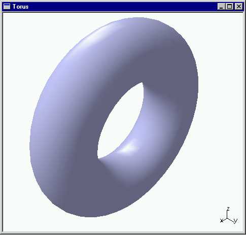
CAAVisBasics includes a MDI interactive application that displays viewers in its document windows. One of these viewers is displayed when the application is launched and contains the representation of a torus. This article focuses on how to create levels of details for this torus, that is several tessellations, each corresponding to a given sag value, in order to the render to select the most appropriate one depending on the viewpoint characteristics and on the object size.
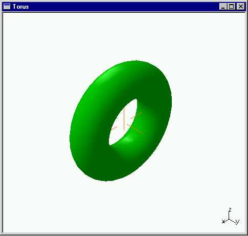
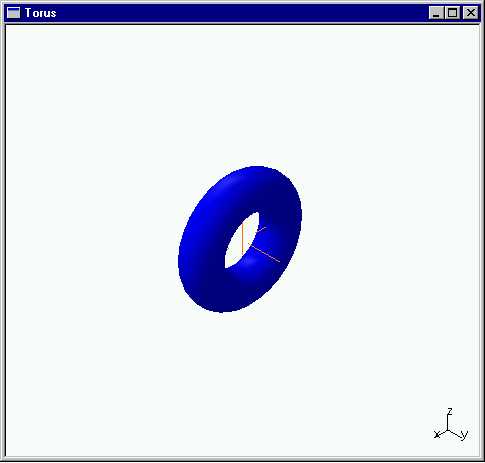
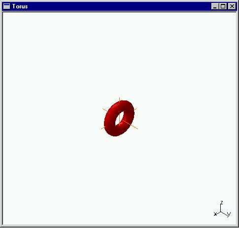
The torus is displayed in a 3D navigation viewer as soon as the application is launched. It is displayed brighter blue with a representation that is computed with a sag of 1/8. When zooming in, the viewpoint characteristics change, and three other representations are successively displayed: a green one with a sag of 1/6, a blue one with a sag of 1/4, and a red one with a sag of 1/2.
[Top]
To launch CAAVisBasics, you will need to set up the build time environment, then compile CAAVisBasics along with its prerequisites, set up the run time environment, and then execute the use case [1].
The torus is displayed in a 3D navigation viewer as soon as the application is launched. Zoom in and out to show the different levels of details and their associated colors.
[Top]
The CAAVisBasics use case is made of several classes located in the CAAVisBasics.m module of the CAAVisualization.edu framework:
| Windows | InstallRootDirectory\CAAVisualization.edu\CAAVisBasics.m\ |
| Unix | InstallRootDirectory/CAAVisualization.edu/CAAVisBasics.m/ |
where InstallRootDirectory is the directory where the CAA CD-ROM
is installed.
This use case deals with the following classes:
| CAAVisBaseApplication | Class for the interactive application that hosts the viewer |
| CAAVisBaseDocument | Class for the document base class |
| CAAVisBaseDefaultDocument | Class for the document that creates a representation and four level of details for a torus model |
| CAAVisBaseView | Class for the document window containing a viewer to display the document |
[Top]
To create levels of details, there are three main steps:
| # | Step | Where |
|---|---|---|
| 1 | Create a CAT3DLodRep | CreateModel method of CAAVisBaseDefaultDocument |
| 2 | Loop for each sag value onto the CAT3DFaceGP creation | CreateModel method of CAAVisBaseDefaultDocument |
| 3 | Create the bounding sphere for each level of details | AddLOD method of CAAVisBaseDefaultDocument |
The torus is displayed when the CAAVisBase application is launched. The torus
levels of details creation and display is performed in the CAAVisBaseDefaultDocument
constructor that creates a CAT3DLodRep instance and that loops on calling
the CreateRep method that creates a CAT3DFaceGP instance
with the passed sag, and that adds it to the CAT3DLodRep instance. The
representation is displayed thanks to calling the AddRepToViewer
method. Only the constructor and the part of CreateRep that deals
with the CAT3DLodRep management are described below. The remaining parts,
namely the torus tessellation and the creation of CAT3DLodRep instance
are already dealt with in [2].
[Top]
The CAAVisBaseDefaultDocument constructor creates the representation
bag to attach to the viewer, creates a CAT3DLodRep instance for the
torus, calls CreateRep as many time as there are sag values to the
corresponding torus representations, adds the resulting 3D Lod representation to
the representation bag, and calls AddRepToViewer for display.
void CAAVisBaseDefaultDocument::CreateModel()
{
  _pRootContainer  = new CAT3DBagRep;
  _pTorusLodRep = new CAT3DLodRep();
  float sag = 0.125f;
  ... // Loop on the torus tessellation
  //Adding of the CAT3DLodRep to the CAT3DBagRep
  _pRootContainer->AddChild(*_pTorusLodRep);

  AddRepToViewer();
}
|
This 3D representation to accommodate the different tessellations of the torus is a CAT3DLodRep instance. This representation is dedicated to contain several representations of the same object, each being associated with the sag value used to create it.
[Top]
...
  int color[3] = {255, 255, 255}; //White color

  int colors[] = {200, 200, 255, //bright blue
                  200, 0,   0,   //red
                  0,   0,   255, //blue
                  0,   200, 0};  //green
  for(int i=NLOD; i>0; i--)
  {
    sag = float(MAX_SAG)/(float)(2*i);
    color[0] = colors[3*(i%NLOD)];
    color[1] = colors[3*(i%NLOD)+1];
    color[2] = colors[3*(i%NLOD)+2];
    AddLOD(sag, color);
  }
...
|
The sag values are computed and passed to the AddLOD method as
well as the associated color.
[Top]
The AddLOD method is the same as the one explained in [2],
except that it has the sag as argument, and computes the theta and phi angles
from the sag value. It also update the 3D Lod representation with the created 3D
custom representation.
void CAAVisBaseDefaultDocument::AddLOD(float sag, int *iColor)
{
  int R = TORUS_RADIUS;
  int r = CIRCLE_RADIUS;

  float theta = sqrt(sag/r);
  float phi   = sqrt(sag/R);

  int nVertexPerCircle = floor(2*PI/theta)+1;
  int nCircles         = floor(2*PI/phi)+1;

  theta = 2*PI/nVertexPerCircle;
  phi   = 2*PI/nCircles;

  ... // Refer to [2] for the 3D graphic primitive and 3D custom representation creation

  _pTorusLodRep->AddLod(_pTorusCustomRep, sag);
}
|
The angles theta and phi are computed using the sag value and the rotating
circle radius and the torus radius respectively. sag/R to be explained.
The number of vertices per circle and the number of circles are deduced from the
angle values. Then, these angle values are adjusted to partition the circles.
The 3D graphic primitive and the 3D custom representation are created as
described in [2]. _pTorusCustomRep is the
pointer to the 3D custom representation. It is added to the 3D Lod
representation along with the associated sag value
[Top]
This use case shows the objects involved when creating several representations for a given object and to bind them in a 3D Lod representation. This enables the object to provide representations that match the different accuracies required when the viewpoint and display characteristics change.
[Top]
| [1] | Building and Launching a CAA V5 Use Case |
| [2] | Tessallating a Torus |
| [Top] | |
| Version: 1 [Feb 2000] | Document created |
| [Top] | |
Copyright © 2000, Dassault Systèmes. All rights reserved.