3D PLM Enterprise Architecture |
3D Visualization |
Tessellating and Displaying a TorusCreating a 3D face graphic primitive and displaying it using a 3D custom representation |
| Use Case | ||
AbstractThis article shows how to create a CAT3DFaceGP class instance to tessellate a torus and how to display it using a CAT3DCustomRep instance. |
This use case explains how to create a CAT3DFaceGP class instance to tessellate a torus and how to display it using a CAT3DCustomRep instance. It show the torus tessellation using a set of triangle strips according to a given sag.
[Top]
CAAVisBasics is a set of use cases of the CAAVisualization.edu framework that illustrates Vizualization framework capabilities.
[Top]
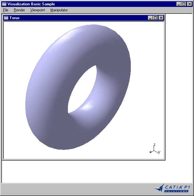
CAAVisBasics includes a MDI interactive application that displays viewers in its document windows. One of these viewers is displayed when the application is launched and contains the representation of a torus. This article focuses on how to create this representation as a CAT3DCustomRep instance associated with a graphic primitive that is an instance of the CAT3DFaceGP class.
The torus is displayed in a 3D navigation viewer as soon as the application is launched.
|
[Top]
To launch CAAVisBasics, you will need to set up the build time environment, then compile CAAVisBasics along with its prerequisites, set up the run time environment, and then execute the use case [1].
The torus is displayed in a 3D navigation viewer as soon as the application is launched.
[Top]
The CAAVisBasics use case is made of several classes located in the CAAVisBasics.m module of the CAAVisualization.edu framework:
| Windows | InstallRootDirectory\CAAVisualization.edu\CAAVisBasics.m\ |
| Unix | InstallRootDirectory/CAAVisualization.edu/CAAVisBasics.m/ |
where InstallRootDirectory is the directory where the CAA CD-ROM
is installed.
This use case deals with the following classes:
| CAAVisBaseApplication | Class for the interactive application that hosts the viewer |
| CAAVisBaseDocument | Class for the document base class |
| CAAVisBaseDefaultDocument | Class for the document that creates a representation and four level of details for a torus model |
| CAAVisBaseView | Class for the document window containing a viewer to display the document |
[Top]
A torus is a solid of rotation made by rotating a circle about an axis located in the plane of the circle.
The torus surface can be described by selecting evenly distributed circles, and by drawing a strip of triangles between each couple of consecutive circles.
The two important parameters of the tessellation are the number of circles, and the number of vertices per circle. The more they are circles and vertices, the more the discretization is precise, but the more the discretization and display processes are costly. In addition, depending on the current zoom, the number of circles and of vertices per circle can be changed to optimize display performance and accuracy. This is possible thanks to levels of details [2], but is not discussed here.
[Top]
| # | Step | Where |
|---|---|---|
| 1 | Create a 3D navigation viewer instance | CreateViewer method of CATVisBaseView |
| 2 | Create a 3D representation bag | CAAVisBaseDefaultDocument constructor |
| 3 | Create and fill in the arrays for the vertex coordinates and the normal components | CreateRep method of CAAVisBaseDefaultDocument |
| 4 | Create and fill in the arrays for the strip triangle vertex indices and the number of vertices per strip | CreateRep method of CAAVisBaseDefaultDocument |
| 5 | Create the graphic primitive and its associated bounding box | CreateRep method of CAAVisBaseDefaultDocument |
| 6 | Set graphic attributes to the graphic primitive | CreateRep method of CAAVisBaseDefaultDocument |
| 7 | Create the 3D custom representation | CreateRep method of CAAVisBaseDefaultDocument |
| 8 | Associate the representation with the graphic primitive | CreateRep method of CAAVisBaseDefaultDocument |
| 9 | Compute the representation bounding box | CreateRep method of CAAVisBaseDefaultDocument |
| 10 | Display the created 3D representation | AddRepToViewer method of CATVisBaseView |
The torus is displayed when the CAAVisBasics application is launched. The
torus creation and display is performed in the CAAVisBaseDefaultDocument
constructor that calls the CreateRep and AddRepToViewer
methods respectively. These two methods are described below.
[Top]
The 3D navigation viewer is an instance of the CATNavigation3DViewer
class. It is created in the CreateViewer method of the CAAVisBaseView
class that is called when the application is launched.
void CAAVisBaseView::CreateViewer()
{
  _pViewer = new CATNavigation3DViewer(this, "3DViewer",
                                      CATDlgFraNoTitle | CATDlgFraNoFrame,
                                      500, 500);
  Attach4Sides(_pViewer);
}
|
The _pViewer pointer to the 3D navigation viewer is kept as a
data member of the CAAVisBaseView class. Its parameter are:
this |
The viewer parent in the dialog containment tree structure and in the command tree structure [a] |
3DViewer |
The viewer identifier |
CATDlgFraNoTitle |
The viewer has no title [b] |
CATDlgFraNoFrame |
The viewer frame is not displayed [b] |
500, 500 |
The viewer width and height expressed in pixels |
The Attach4Sides method attaches the four sides of the viewer to
those of the window. This makes the viewer occupy the whole window space.
[Top]
The CAAVisBaseDefaultDocument constructor creates the representation
bag to attach to the viewer, calls CreateRep to create the torus
representation, adds it to the representation bag, and calls AddRepToViewer
for display.
CAAVisBaseDefaultDocument::CAAVisBaseDefaultDocument(CATCommand * iParent,
                                                     CATDialog  * iDialogParent,
                                                     CATString  * const iDocumentName)
                         : CAAVisBaseDocument(iParent, iDialogParent, iDocumentName)
{
  _pRootContainer  = new CAT3DBagRep();
  CreateRep();
  _pRootContainer->AddChild(*_pTorus);
  AddRepToViewer();
}
|
Let's examine what CreateRep does.
[Top]
First set the tessellation parameters.
void CAAVisBaseDefaultDocument::CreateRep()
{
  int R = TORUS_RADIUS;
  int r = CIRCLE_RADIUS;

  float teta = sqrt(sag/r);
  float phi  = sqrt(sag/R);

  int nVertexPerCircle = floor(2*PI/teta)+1;
  int nCircles         = floor(2*PI/phi)+1;

  teta = 2*PI/nVertexPerCircle;
  phi  = 2*PI/nCircles;
...
|
The tessellation parameters are nVertexPerCircle (number of
vertices per circle), and nCircles (total number of circles). They
determine the two angles theta and phi:
2*Pi/nVertexPerCircle).
It determines the sag parameter for the circle discretization, that is the
distance between the chord joining two vertices, that is displayed to
represent the circle, and the actual circle |
 |
And now fill in the arrays.
...
  //array containing the vertices coordinates:
  int verticesArraySize = 3*nCircles*nVertexPerCircle;
  float * vertices = new float[verticesArraySize];

  //array containing the normals to each vertex:
  int normalsArraySize = 3*nCircles*nVertexPerCircle;
  float * normals = new float[normalsArraySize ];

  for(int i=0; i<nCircles; i++)
  {
    for(int j=0; j<nVertexPerCircle; j++)
    {
      //vertex XYZ coordinates
      vertices[3*(nVertexPerCircle*i+j)]   = (R+r*cos(j*theta))*sin(i*phi);
      vertices[3*(nVertexPerCircle*i+j)+1] = r*sin(j*theta);
      vertices[3*(nVertexPerCircle*i+j)+2] = (R+r*cos(j*theta))*cos(i*phi);

      //normal vector XYZ components
      normals[3*(nVertexPerCircle*i+j)]   = cos(j*theta)*sin(i*phi);
      normals[3*(nVertexPerCircle*i+j)+1] = sin(j*theta);
      normals[3*(nVertexPerCircle*i+j)+2] = cos(j*theta)*cos(i*phi);
    }
  }
...
|
The vertex coordinates are stored in the vertices array. The
first vertex x, y, and z coordinates are stored in the first three array
elements, then the second vertex coordinates are stored in the following three
array elements, and so on. The normal components are stored in the normals
array in the same way than the vertex coordinates. The coordinates of a given
vertex occupies the same array elements in the vertices array than
the components of the normal at this vertex in the normals array.
[Top]
The vertex indices of the triangle strips are stored in the vertex index array. They are used to scan the vertex and normal arrays when the graphic primitive is built. Vertices and normals are then used for display in the order read from the vertex index array.
...
  // Creation of the torus representation thanks to the CAT3DFaceGP.
  // We can build a CAT3DFaceGP made of nCircles triangles strips, each one
  // made of 2*nVertexPerCircle vertices. Indeed, by joining, with strips, the torus circles
  // two by two, we can describe the entire torus.

  // We have to build an array containing the vertices indices, sorted in
  // order to be parsed as strips vertices.

  //Array containing vertices indices:
  int * triangleStripIndices = new int[nCircles*2*(nVertexPerCircle+1)];
  //number of strips used to describe the torus:
  int nbTriangleStrip = nCircles;
  //Array containing the number of vertices used for each strip:
  int * nbVertexPerTriangleStrip = new int[nCircles];

  // the parsing order looks like this:
  //
  //           first strip:
  //           -----------
  //   Circle0.Vertex0  -> Circle1.Vertex0
  //   Circle1.Vertex0  -> Circle0.Vertex1
  //   Circle0.Vertex2  -> Circle1.Vertex2    Circle0.Vertex1  -> Circle1.Vertex1
  //               ...                        Circle1.Vertex1  -> Circle0.Vertex2
  //   Circle1.Vertex11 -> Circle0.Vertex0
  //   Circle0.Vertex0  -> Circle1.Vertex0
  //
  //           second strip:
  //           ------------
  //   Circle1.Vertex0  -> Circle2.Vertex0
  //   Circle2.Vertex0  -> Circle1.Vertex1
  //               ...

  for(i=0; i<nCircles; i++)
  {
    for(int j=0; j<=nVertexPerCircle; j++)
    {
      if(j<nVertexPerCircle)
      {
        triangleStripIndices[2*(nVertexPerCircle+1)*i+2*j]   = 3*(i*nVertexPerCircle+j);
        triangleStripIndices[2*(nVertexPerCircle+1)*i+2*j+1] = 3*((((i+1)%nCircles)*nVertexPerCircle)+j);
      }
      else
      {
        triangleStripIndices[2*(nVertexPerCircle+1)*i+2*j]   = 3*((i)*nVertexPerCircle);
        triangleStripIndices[2*(nVertexPerCircle+1)*i+2*j+1] = 3*(((i+1)%nCircles)*nVertexPerCircle);
      }
    }
    nbVertexPerTriangleStrip[i] = 2*(nVertexPerCircle+1);
  }
...
|
The vertex index array to create the triangle strips is filled in following
the vertex scanning order shown in Fig. 3. Each couple of
adjacent circles is processed until reaching the first circle to close the
torus. For each couple of circles, the indices successively stored designate a
vertex on the first circle and its counterpart on the second one until reaching
the first vertices on each circle. The index of a vertex is the index of its x
coordinate in the vertices array. This table thus begins by 0, 240,
3, 243, 6, 246, ... and so on. The (i+1)%nCircles modulo operation
always returns i+1, except when i is equal to nCircles-1
where it returns 0 to get the first circle. The array containing the number of
vertices per strip has nCircles elements that all have the same
value 2*(nVertexPerCircle+1), that is 162, since the first two
vertices are counted twice.
[Top]
The graphic primitive is created using the arrays computed in the previous steps.
...
  // Creation of the CAT3DFaceGP:

  int * triangleIndices = NULL;
  int nbTriangle = 0;
  int * triangleFanIndices = NULL;
  int nbTriangleFan = 0;
  int * nbVertexPerTriangleFan = NULL;
  float TextureCoord = NULL;
  int   TextureFormat = 3;

  CAT3DFaceGP * pFace = new CAT3DFaceGP(vertices,
                                        verticesArraySize,
                                        normals,
                                        normalsArraySize,
                                        triangleIndices,
                                        nbTriangle,
                                        triangleStripIndices,
                                        nbTriangleStrip,
                                        nbVertexPerTriangleStrip,
                                        triangleFanIndices,
                                        nbTriangleFan,
                                        nbVertexPerTriangleFan,
                                        TextureCoord,
                                        TextureFormat,
                                        ALLOCATE_VERTICES | ALLOCATE_NORMALS
                                        );
  pFace->ComputeBox();
...
|
The computed arrays are passed as constructor parameters, along with their
sizes. Since the graphic primitive is not built using isolated triangles or
triangle fans, the corresponding arrays are passed as NULL
pointers, and their sizes and the triangle fan number as 0. No texture
coordinates are passed. The vertex and normal arrays default allocation mode is
explicitly used to show that the created graphic primitive allocates the arrays.
In this case, there is no need to allocate them using the new operator. The
graphic primitive bounding box is computed as soon as graphic primitive is
created.
[Top]
The graphic attribute set can be customized.
... CATGraphicAttributeSet pGraphicAttributes; //We specify within the graphic attributs that our surface is a SOLID. pGraphicAttributes.SetType(3); //In order to be able to see each LOD, we specify a different color //for each LOD: pGraphicAttributes.SetColor(TRUECOLOR); //Red for the most precise model. pGraphicAttributes.SetColorRGBA(255, 0, 0, 255); ... |
The value 3 passed as the parameter of SetType indicates that
the graphic primitive is a volume and participates to the ZBuffer. The graphic
primitive color scheme is set as true color, and its color is set to red using
the red color RGB components (255, 0, 0). The last parameter is the default
value for alpha blending.
[Top]
... CAT3DCustomRep * _pTorusCustomRep = new CAT3DCustomRep(); // ou CAT3DCustomRep(pFace, pGraphicAttributes); ... |
The custom representation to accommodate the graphic primitive is a 3D custom representation.
[Top]
... _pTorusCustomRep->AddGP(pFace, pGraphicAttributes); ... |
The representation is associated with the graphic primitive and its graphic attribute set.
[Top]
The representation needs a bounding box to improve the display process.
...
  //We MUST create the associated bounding box:
  float center[3] = {0.0, 0.0, 0.0};
  float radius = R+r;
  CAT3DBoundingSphere bs(center, radius);
  _pTorusCustomRep->SetBoundingElement(bs);
  _pTorusCustomRep->SetGraphicAttributeSet(pGraphicAttributes);

  delete [] vertices;
  delete [] normals;
  delete [] triangleStripIndices;
  delete [] nbVertexPerTriangleStrip;
}
|
This bounding box is the sphere whose center is the torus center, and whose radius is the external torus radius.
[Top]
The AddRepToViewer method displays the created representation.
void CAAVisBaseDocument::AddRepToViewer()
{
  _pView->Add3DRep(_pRootContainer);
}
|
_pView is a pointer to the 3D navigation viewer. The
representation is assigned to this viewer thanks to the Add3DRep
method.
[Top]
This use case shows the objects involved when tessellating a torus, and the tessellation process, namely a 3D navigation viewer instance, a 3D representation bag, how to create vertices, normals, and strip triangles, how to create the graphic primitive and its associated bounding box to accommodate the torus, how to set its graphic attributes, how to create the 3D custom representation from the graphic primitive and its graphic attributes, compute the representation bounding box, and display the representation.
[Top]
| [1] | Building and Launching a CAA V5 Use Case |
| [2] | Creating Levels of Details |
[Top]
| Version: 1 [Feb 2000] | Document created |
| [Top] | |
Copyright © 2000, Dassault Systèmes. All rights reserved.