Mechanical Design |
Assembly Design |
Creating a Parallelism Constraint in an AssemblySet a parallelism constraint between an assembly component and a plane |
| Use Case | ||
AbstractThis article discusses the CAAAuiCreateCstOnParts use case. This use case explains how to create an assembly parallelism constraint in a Product document. |
This use case is intended to help you make your first steps in programming with CATIA Assembly Design. Its main intent is to create geometrical relations between products. More specifically, you will learn how to:
[Top]
CAAAuiCreateCstOnParts is a use case of the CAAAssemblyUI.edu framework that illustrates the CATAssemblyInterfaces framework capabilities.
Before discussing the use case, some main concepts have to be introduced:
A parallelism constraint is a geometrical relation created between two components
Making parallel two components means creating a geometrical parallelism between two geometrical elements, one in the first component and the other in the second one, such as lines, planes, etc.
The constrained components must be child components of the active component
To create a constraint between two components, a connector must be created in each of these components, and the constraint will apply to the components through these connectors.
[Top]
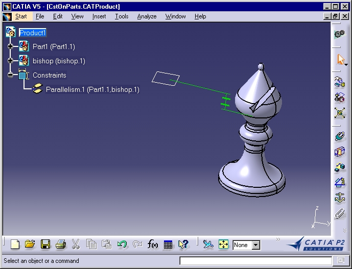
CAAAuiCreateCstOnParts:
The parallelism constraint appears in the specification tree at the same level as the child components and they are displayed in the geometry.
These concepts are the counterpart, on the programming side, of what the end users sees and manipulates on the screen. So we will start with the end user view in order to infer what the program manipulates inside.
[Top]
To launch CAAAuiCreateCstOnParts, you will need to set up the build time environment, then compile CAAAuiCreateCstOnParts along with its prerequisites, set up the run time environment, and then execute the use case [1].
Launch the use case as follows:
e:>CAAAuiCreateCstOnParts InputDirectory\Fou.CATPart OutputDirectory\ |
$ CAAAuiCreateCstOnParts InputDirectory/Fou.CATPart OutputDirectory/ |
where:
InputDirectory |
The directory into which Fou.CATPart is stored, usually in the resources directory of your RuntimeView |
OutputDirectory |
The directory where you want to store the created CATProduct |
[Top]
The CAAAuiCreateCstOnParts use case is located in the CAAAuiCreateCstOnParts.m module of the CAAAssemblyUI.edu framework:
| Windows | InstallRootDirectory\CAAAssemblyUI.edu\CAAAuiCreateCstOnParts.m\ |
| Unix | InstallRootDirectory/CAAAssemblyUI.edu/CAAAuiCreateCstOnParts.m/ |
where InstallRootDirectory is the directory where the CAA CD-ROM
is installed.
[Top]
There are five main steps in CAAAuiCreateCstOnParts:
We will now comment each of those sections by looking the code.
[Top]
CAAAuiCreateCstOnParts begins by checking that the command lines contains two
arguments. It then creates a session, and creates a new Product document,
reffered to using a pointer to the CATDocument class named pDoc,
and retrieves the document's root product handled using the piProductOnRoot
pointer. This is the usual sequence for creating a Product document and
accessing its root product [2] [3].
Then, a new part component and an existing part component are successively added
to the product structure [3]. The following variables
are created to be used in the following steps:
piInstanceProd1 |
A pointer to CATIProduct onto the part component created from an empty part |
piInstanceProd2 |
A pointer to CATIProduct onto the part component created from the existing Bishop part |
pPartDoc2 |
A pointer to CATDocument onto the existing Bishop part document |
[Top]
  ...
  CATIConnector * pConnector1 = NULL;
  CATILinkableObject_var spLO_InstProd1;
  if( SUCCEEDED(piInstanceProd1->GetShapeRep(spLO_InstProd1, "Default", CATPrd3D, TRUE)) )
  {
    CATIPrtPart *pPart_InstProd1 = NULL;
    rc = spLO_InstProd1->QueryInterface(IID_CATIPrtPart, (void **) &pPart_InstProd1);
    if( SUCCEEDED(rc) )
    {
      CATListValCATISpecObject_var spListRefPlanes = pPart_InstProd1->GetReferencePlanes();
      // defines the yz plane as the first sketch plane
      CATILinkableObject *pLO_xYPlane = NULL;
      if( spListRefPlanes.Size() )
      {
        CATISpecObject_var spXYPlane = spListRefPlanes[1];
        if( spXYPlane != NULL_var )
        {
          rc = spXYPlane->QueryInterface(IID_CATILinkableObject ,(void **) &pLO_XYPlane);
          if ( SUCCEEDED(rc) )
          {
            int iCreation = 0;
            rc = ::GetProductConnector(pLO_XYPlane,
                                       piInstanceProd1,
                                       piProductOnRoot,
                                       0,
                                       pConnector1,
                                       iCreation);
            pLO_XYPlane->Release();
            pLO_XYPlane = NULL;
          }
        }
      }
      pPart_InstProd1->Release();
      pPart_InstProd1 = NULL;
    }
  }
  ...
|
The XY plane is accessed by scanning the Part document structure [4].
First we retrieve the shape representation of piInstanceProd1,
which is the Mechanical Part and ask it a pointer to CATIPrtPart. Then we
get the reference planes thank to and keep the first one, which is the XY
plane. A CATILinkable pointer is retrieved from the plane
and is used to create the connector using the GetProductConnector
global function, whose arguments are:
spiLinkableOnPlane |
The geometric object onto which the connector is to be created or retrieved. This object must be linkable to ensure its stability during sessions |
piInstanceProd1 |
The component instance containing the geometric object above |
piProductOnRoot |
The active component, here the Product document's root product |
0 |
The searching mode: set to 0, it requests the function to create the connector if no connector exists that matches the preceding arguments |
piConnector1 |
The resulting connector, as a pointer to CATIConnector |
creationStatus |
This is an output parameter. It is set to 1, meaning that the connector has been created |
[Top]
  ...
  CATInit * piInitOnDoc = NULL;
  rc = pPartDoc2->QueryInterface(IID_CATInit, (void**)&piInitOnDoc2);
  if ( SUCCEEDED(rc) )
  {
    CATIPrtContainer *piPrtContainerOnRoot =
     (CATIPrtContainer*)piInitOnDoc2->GetRootContainer("CATIPrtContainer");
     piInitOnDoc2->Release();

    CATIPrtPart_var spiPrtPartOnPartBody (NULL_var);
    if( NULL != piPrtContainerOnRoot )
    {
      spiPrtPartOnPartBody = piPrtContainerOnRoot->GetPart();
      piPrtContainerOnRoot->Release();
    }
    CATIDescendants *piDescendantsOnPart= NULL;
    CATLISTV(CATISpecObject_var) Planes;
    CATILinkableObject_var  spiLinkableOnPlane (NULL_var);
    CATIConnector * piConnector2 = NULL;
    if( SUCCEEDED(spiPrtPartOnPartBody->QueryInterface(IID_CATIDescendants,
                                                       (void**)&piDescendantsOnPart)) )
    {
      piDescendantsOnPart->GetAllChildren("CATPlane", Planes);
      piDescendantsOnPart->Release();
      if (Planes.Size())
      {
        int creationStatus = 0;
        spiLinkableOnGeometry = Planes[1];
        if ( NULL_var != spiLinkableOnGeometry )
        {
          ::GetProductConnector((CATILinkableObject *)spiLinkableOnPlane,
                                 piInstanceProd2,
                                 piProductOnRoot,
                                 0 ,
                                 piConnector2,
                                 creationStatus);
        }
      }
    }
  }
  ...
|
The plane onto which a connector will be created is retrieved by scanning the
Part document structure [4]. First, we have a pointer,
pPartDoc2, to the CATInit interface onto the Part document,
and the Part document root container is retrieved as a pointer to CATIPrtContainer
thanks to the GetRootContainer method of CATInit. Then the
Mechanical Part is retrieved from this container as a CATIPrtPart smart pointer
thanks to the GetPart method of CATIPrtContainer. The
Mechanical Part is asked for a pointer to the CATIDescendants interface that enables
a collection of all the objects that implement the CATPlane interface to
be retrieved thanks to the GetAllChildren method. If at least one
plane is retrieved, a CATILinkable pointer is retrieved from the plane
and is used to create the connector using the GetProductConnector
global function, whose arguments are:
spiLinkableOnPlane |
The geometric object onto which the connector is to be created or retrieved. This object must be linkable to ensure its stability during sessions |
piInstanceProd2 |
The component instance containing the geometric object above |
piProductOnRoot |
The active component, here the Product document's root product |
0 |
The searching mode: set to 0, it requests the function to create the connector if no connector exists that matches the preceding arguments |
piConnector2 |
The resulting connector, as a pointer to CATIConnector |
creationStatus |
This is an output parameter. It is set to 1, meaning that the connector has been created |
[Top]
  ...
  CATLISTV (CATBaseUnknown_var) ConnectorList;
  ConnectorList.Append(spiConnector1);
  ConnectorList.Append(piConnector2);
  piConnector2->Release();

  CATIAConstraint *piCst = NULL;
  rc = ::CreateConstraint(catCstTypeParallelism,
                          ConnectorList,
                          NULL,
                          piProductOnRoot,
                          piCst);
  ...
|
To create a constraints, the connectors must be first put in a collection.
Then, the constraint can be created using the CreateConstraint
global function. CreateConstraint has the following arguments.
catCstTypeParallelism |
The constraint's type: a parallelism constraint. |
ConnectorList |
The list which contains the connectors involved in the constraint. |
NULL |
The constraint's value. For angle or offset constraints only. |
piProductOnRoot |
The active component under which the constraint is inserted in the sprecification tree |
piCst |
The resulting constraint |
[Top]
The three documents created are saved:
| Bishop.CATProduct | The Product document that contains the Bishop part |
| Part1.CATProduct | The Product document that contains the empty part |
| CstOnParts.CATProduct | The Product document that contains the assembly with the constraint created |
Then, the session is closed, as usual [5].
[Top]
This use case has demonstrated the way to constrain two components of an assembly, by creating a connector onto a geometric object in each of the products to constrain, and creating a constraint using these two connectors.
[Top]
| Version: 1 [Jan 2000] | Document created |
| [Top] | |
Copyright © 2000, Dassault Systèmes. All rights reserved.