 |
This task shows
you how to route using flexibles. |
 |
Flexibles can be
routed in space, from another part (tube, conduit or waveguide) or from an
item reservation (you may need to add a connector). When you route a
flexible you are placing the actual part, such as a tube. A run is
not created when you route a flexible. The first and last points of a flexible tube can either be a
3D point in space, an indication point, or a connector that contains a
datum point. The inner points can be a 3D point selection or an
indication in space on the current compass plane. |

|
1. |
To begin routing in space, click the Flexible Routing
button  . The
Flexible Routing dialog box opens. . The
Flexible Routing dialog box opens.
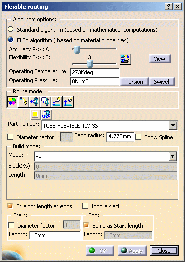
- Standard Algorithm: If you use this option
then the routing is based on mathematical calculations only. This
means that the physical properties of the part you are using are not
taken into account when routing. This was the only method used in
Version 4, and up to Version 5 Release 16.
- FLEX algorithm: This is available from
Version 5 Release 17 onward. The physical properties of the part you are using
are taken into account when routing. Properties like material,
gravity, pressure rating and operating temperature of the flexible
are considered. You can set the direction in which the slack will
sag by using a setting. Click Tools - Options, select
Equipment & Systems and the Design Criteria
tab. Under Flexible Routing Options click on the down
arrow and select the direction in which the slack will sag - X,
Y or Z. NOTE: This option is only available if you have
the FLX license installed. If you do not have the license then
routing will use the standard algorithm.
- Accuracy: Moving the slider to the right increases
accuracy. Greater accuracy will give you a smoother flexible. It will also
degrade performance.
- Flexibility: If the material on the flexible you are
using is not defined, then you can use this slider to set
flexibility. Moving the slider to the right increases flexibility.
If you want routing to take into account the material defined for
the flexible then you need to select the Use
Material Associated to Part
button
 .
If the button is not selected then routing will take into account
the position of the slider. .
If the button is not selected then routing will take into account
the position of the slider.
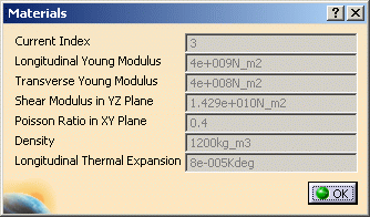
- Click the View button to display material properties.
- Enter values in the Operating Temperature
and Operating Pressure fields.
- Select Torsion and
Swivel properties if necessary.
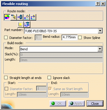
If you do not have the FLX license then the following dialog box will
display:
 |
| |
2. |
Select a routing mode.
- Select or Indicate allows you to
click the mouse button to indicate routing points. You can also select
connectors.
- Use Select 3D Point Only if you want to select 3D points as routing
indicators. See Routing Flexibles from a
Connector.
- Select a Connector Only lets you select a connector to route from:
see Routing Flexibles from a Connector.
- Part Connector Dialog lets you select a connector to route from: see Routing Flexibles from a
Connector.
- See Routing Flexibles with an Offset for more
information about offsetting.
|
| |
3. |
Click the Spec Driven button if you want your selected specifications
catalog to apply. If you do not select it then all parts, based on your
filters, will be available to you. NOTE: HVAC Design is always
specification-driven and the button will not display. Click the Filter Definition button to
bring up the Filter Definition dialog box. This allows you to filter by
attribute and value. |
| |
4. |
Click the down arrow next to the Part Number field and select a part, then
define the following parameters:
- Check the Diameter Factor box and enter a value - this will define
the bend radius (the bend radius will be the factor multiplied by the
part size). If you do not check this box then the bend radius will be
derived from the bending rule table.
- Bend radius: Instead of entering the diameter factor you can enter
the actual bend radius value. You must use the Bend mode (see below) in
this case.
- Show Spline: Check this checkbox to display the spline of the routed
flexible.
|
| |
5. |
Define the build mode parameters.
- Use Length mode when you know the fixed length of the
flexible tube. You need to enter a value in the Length field.
- Use Slack mode - and enter a value in the Slack field - to add additional length to the minimum
length. If you use 0 slack between two defining points, the spline
will be straight. If you define the flexible using two points, and the
distance between the points is 40in, and you set the slack mode to 50%,
the new length will be 60in.
- If you select the Bend mode, the bend radius
will equal the value in the Bend Radius field and, additionally, the
flexible will find the minimum distance between the points defining the
route.
|
| |
6. |
If you check the Ignore Slack checkbox when routing then that
particular segment will have no slack in it. This option can only be used
a segment at a time while routing. |
| |
7. |
You can have a
specified straight length at the ends, such as where a tube connects to
an object. If you do not specify a straight length then the tube may
angle out from the object, instead of being straight. If you
want straight lengths at the ends, then check the Straight Length
at Ends
checkbox and enter values as follows.
- Diameter factor - If you check this box and enter a value then both the
start and end of the tube will have a straight length determined by your
factor. If the tube diameter is 10 mm, and you enter a factor of 1, then
10 mm of the tube will be straight at the ends.
- You can enter the Start and End lengths if you prefer. Make sure the
Diameter Factor checkbox is unchecked and enter a value in the
Start field. If you want the same value in the End
field then check Same as Start
Length. If you want a different value then uncheck this box and
enter a value in the End field.
|
|
8. |
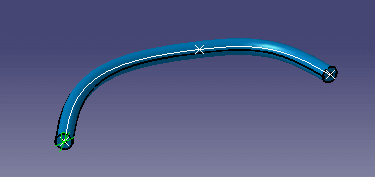
Click in space where you want to begin your route and click
two more points to create a simple run. Click Apply. Your
flexible run should look similar to this.
|
|
9. |
In the Build Mode area of the Flexible Routing dialog
box, change the value in the Slack % field to 20 and click Apply.
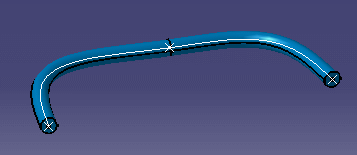
The tube adjusts to reflect the additional slack. Note that the
selected points remain in position. Now, change the Mode to Length to
increase the value and click Apply. Now the slack value will
increase and the run will be updated. To adjust the slack of a segment see
the section on Managing Local Slack. |
|
10. |
Click OK when finished. |
|
 |
|


