This section gives you information about the Data Mapping
process.

What is Data Mapping?
Data Mapping is a functionality allowing load import described by a
scalar field from a text (.txt) or an Excel (.xls) file. This file must
respect a pre-defined format.
You can re-use data that are external data (experimental
data or data coming from in-house codes or procedures).
The imported values will be interpolated at the center of gravity of each
element.
You can also integrate user loading knowledge and processes into this
version.
The selected external data file will be either a .txt
file (columns separated using the Tab key) or a .xls
file. This file must respect a pre-defined format.
Data Mapping is useful when you want to re-use a load field
created without CATIA or with a former version of CATIA. |

Data Mapping files are text files (.txt) or Excel files (.xls) that must
respect a pre-defined format.
- For pressure, line force density, surface force density, body load,
temperature and shell property functionalities, the data mapping file
must respect the following format:
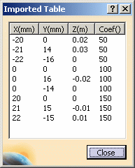
- Four columns.
- Each cell must contain a numerical value.
- The first three columns allow you to specify X, Y
and Z point coordinates in the global axis.
Unit symbol written between parentheses must be specified.
- The last one allows you to specify the amplification coefficient.
No unit symbol must be specified for the last column (the amplification
coefficient is not assigned to a dimensional value).
Example of data mapping for a pressure:

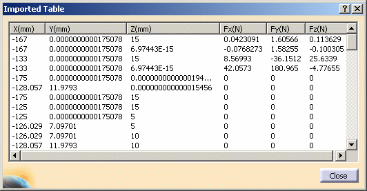
Example of data mapping for an imported force:

|

Which algorithm is used for Data Mapping?
There are three steps in this algorithm:
-
Checking that the center of gravity of each entity of the
recipient mesh is inside the axis-aligned bounding box of the source mesh
(automatic tolerance: 1.0 e-3 m).
 |
An entity can be an element, an edge or a face.
For example, in the case of:
- a temperature field, entity means element,
- a line force density, entity means edge,
- a pressure, entity means face.
|
-
Matching the center of gravity of each entity of the
recipient mesh with some of the nearest points of the scalar field.
 |
- These points are processed as if they were the vertices of a
finite element.
- The matching is done at the centers of gravity of the recipient
mesh entities, and not at their nodes, because it is the resulting
loads location.
|
-
Interpolating the scalar field of the source mesh on the
recipient mesh using the nodal functions of the finite element.
|

In which functionalities is the Data Mapping
process available?
The Data Mapping process is available in the following functionalities:
|
![]() .
.