This task shows you how to create and edit local sensors.
A local sensor is a physical output (stress, strain, force, ...) of the computation limited to a local area (body, edge, face, vertex, mechanical feature), on which a post-treatment has been optionally applied (Max, Min, Average, ...).
The local sensors can be used either in a mono-occurrence computed solution (static solution without multi loads set) or multi-occurrence computed solution (multi loads static, frequency, buckling or dynamic solution):
Usually, the list of the available sensors depends on the
installed products and the analysis cases. But some particular
characteristics of the model (solid, contact, beam, ...) may modify this
list.
For example:
-
Clearance sensor is only available with a model containing contact
-
Rotation Vector sensor is only available with shell and beam specifications
-
Relative sensors only appear in dynamic cases with restraint excitations.
Local Sensors |
Required License |
Analysis Cases |
|
Displacement Magnitude |
GPS |
All |
|
Force |
EST |
Static |
|
Von Mises Stress |
GPS |
Static |
|
Elastic Energy |
EST |
|
|
Error |
GPS |
Static |
|
Clearance |
EST |
Static |
|
Relative Displacement Vector |
GPS |
Dynamic |
|
Acceleration Vector |
EST |
Mono-occurrence:
The creation of knowledge parameters is restricted to:
- A single point support
- Other support type only if the post-treatment is different of none.
Multi-occurrence:
The creation of knowledge parameters and the generation of a 2D Display are restricted to:
- A single point support
- Other support type only if the post-treatment is different of none.
For more details about the 2D Display generation, refer to Generating 2D Display for Sensors.
Open the sample08.CATAnalysis document from the samples directory for this task.
-
Compute all the solutions.
To do this, click Compute and select the All option.
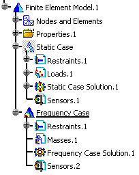
You will now see two examples of local sensor creation in case of mono-occurrence solution and in case of multi-occurrence solution.
Mono-occurrence Solution
-
Set the static case as the current one.
To know more, refer to Changing a Current Analysis Case.
-
Right-click Sensors.1 in the specification tree and select Create Local Sensor.
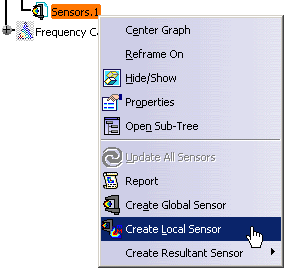
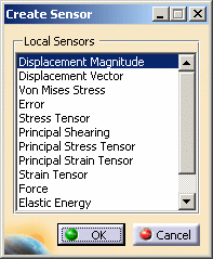
The Create Sensors dialog box appears.
-
Select the desired local sensor and click OK.
In this example, select the Displacement Vector local sensor.
The Displacement Vector object appears in the specification tree.
The Displacement Vector sensor is not yet valid. To make it valid, you have to edit it.
-
Double-click Displacement Vector.1 in the specification tree.
The Local Sensor dialog box appears.
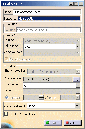
- Name: gives you the name of the sensor.
- Supports: gives you the support definition (vertex, edge, face, body, group, feature).
- Solution: gives you the name of the solution on which you are working.
- Values: to know more, click Advanced Edition.
- Filters: to know more, click Advanced Edition.
- Post-Treatment: lets you take the minimum, maximum or average value of the results.
- Create Parameters: lets you generate, when it is possible, knowledge parameters.
-
Select the desired parameters in the Local Sensor dialog box.
In this particular example:
- Select a face as Support.
- Select Real as Value type.
- Select All as Components.
- Select Maximum as Post-Treatment.
- Click the Create Parameters check box.
-
Click OK.

The OK button is read only in the Local Sensor dialog box as long as the sensor is not valid.
-
Update the Displacement Vector local sensor.
A knowledge parameter appears in the specification tree without associated value.

-
Double-click Displacement Vector.1 in the specification tree.
-
Select C1 as Components option and click OK.
-
Update the Displacement Vector.1 local sensor.
A label containing the maximum value appears on the geometry.
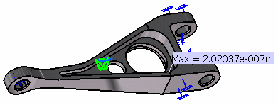

This visualization type is only available if the local sensor:
-
is created in case of mono-occurrence solution
-
is defined with any of the Components options except the All option
-
is defined with a Minimum or Maximum Post-Treatment value
-
is updated.
-
-
You can update a sensor (you just have created or modified) or you can update all the sensors belonging to a sensor set.
-
You can display the value of knowledge parameters in the specification tree.
For more details, refer to Displaying Values of Sensors. -
You can also export data associated to a local sensor (only available with the ELFINI Structural Analysis (EST) product).

The Export Data contextual menu is only available on mono-occurrence local sensor without post-treatment.
To export data on local sensor, right-click a local sensor in the specification tree and then select the Export Data contextual menu
 .
.
![]()
Multi-occurrence Solution
-
Set the frequency case as the current one.
To know more, refer to Changing a Current Analysis Case.
-
Right-click Sensors.2 in the specification tree and select Create Local Sensor.
The Create Sensors dialog box appears.
-
Select the desired local sensor in the Local Sensor dialog box.
In this example, select Von Mises Stress and click OK.
The Von Mises Stress.1 object appears in the specification tree.
The Von Mises Stress.1 is not yet valid. To make it valid, you have to edit it.
-
Double-click the Von Mises Stress.1 object in the specification tree.
The Local Sensor dialog box appears.
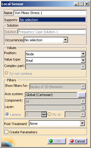
- Name: gives you the name of the sensor.
- Supports: gives you the support definition (vertex, edge, face, body, group, feature).
- Solution: gives you the name of the solution on which you are working.
- Occurrences: lets you take into a selection of
occurrences.
To know more, refer to Selecting Occurrences. - Values: to know more, click Advanced Edition.
- Filters: to know more, click Advanced Edition.
- Post-Treatment: lets you take the minimum, maximum or average value of the results.
- Create Parameters: lets you generate, when it is possible, knowledge parameters.
-
Select the desired parameters in the Local Sensor dialog box.
In this particular example:
- Select a vertex as Support.
- Select All as Occurrences.
- Select Node as Position.
- Select Real as Value type.
- Select Maximum as Post-Treatment.
- Click the Create Parameters check box.
-
Click OK.
-
Update the Von Mises Stress.1 local sensor.

Note that the ListSize knowledge parameter appears in the specification tree without value (in this case, value means the list size).
To display the list size value, refer to Displaying Values of Sensors. -
Double-click Von Mises Stress.
The List Edition dialog box appears.
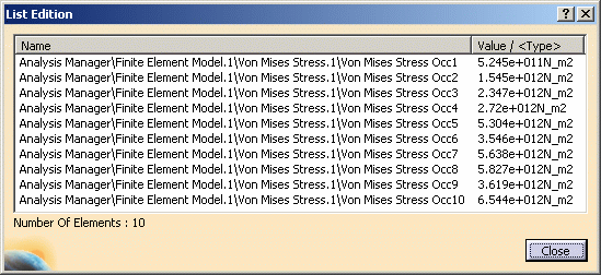
You can see the value of each selected occurrence.
-
Click Close.
-
You can update a sensor (you just have created or modified) or you can update all the sensors belonging to a sensor set.
-
You can display the value of knowledge parameters in the specification tree.
For more details, refer to Displaying Values of Sensors.
![]()