 |
This
task shows you how to:
A 1D property is a physical property assigned to a
section of a part. You can also associate a local 1D property to a piece
of the geometry.
To know more about this property, refer to
Beam Property in the Finite Element Reference Guide. |

|
Open the
sample52.CATAnalysis document from the sample directory. |
 |
-
Make sure a material was applied to the geometry and a
linear 1D mesh part was assigned to the beam (it is already done in
this particular case).
To know more about linear 1D mesh part, refer to
Creating 1D Mesh Parts in
this guide.
-
You cannot apply 1D properties and 1D mesh parts on
geometry included in a sketch.
|
| |
Adding 1D Physical
Properties
You can add 1D physical properties to a shape design by
selecting a meshed wireframe geometry. |
 |
-
Click 1D Property
 in the Model Manager toolbar.
|
The 1D Property dialog box appears.
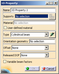
- Name: lets you modify the name of the property.
- Supports: lets you select a support.
- Select Mesh Parts: this button is only available
if you have selected a support.
For more details, refer to Selecting
Mesh Parts.
- Material: indicates you that a material has been
applied.
 |
If you do not specify a user material, the
material taken into account will be the first one found, if
any, on the way up from the selected geometry in the
specification tree. |
- User-defined material: lets you select an
isotropic material that you have created.
For more details, refer to Creating an
User Material.
- Type: lets you choose the type of section (and
symbol) and define the parameters using the Component
Edition button
 . .
For more details about the Type options, refer to
1D Property Section Type.
If you select a geometry option, all the data of
the user-defined beam are computed.
|

|
Additional options available with the ELFINI Structural Analysis
(EST) product:
- Offset: lets you define or not offset values at
each end of the beam.
- None: no offset will be defined.
- Customized: lets you customize the offset values
by clicking the Component Edition button.
- Released DOF: lets you release or not the degrees
of freedom.
- None: no degree of freedom will be released.
- Customized: lets you choose the degrees of
freedom you want to release by clicking the Component
Edition button.
- Variable beam factors: lets you create a linear
approximation of variable cross section beams.
 |
This option is not authorized:
- with the following section types: User-defined
beam, Beam from surface and Variable
beam.
- for discontinuous supports (e.g. a join constituted of
two different lines).
|
|
If you activate this option, two new fields
appear in the Beam Property dialog box.

The Multiplication Factors on
Extremities frame lets you give a scaling factor on
each side of the section. The beam is modeled as a
sequence of constant section beams. For each beam elements,
the cross sectional area is computed at the center of
elements (and not at the node of elements):
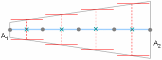
 symbolizes the node of elements and
 symbolizes the center of elements.
A1 = A x f1 and
A2 = A x f2
where:
- A is the specified cross-sectional area
- f1 is the Starting factor
- f2 is the Ending factor.
|
|
-
Select the support geometry to be applied a 1D
property.
|

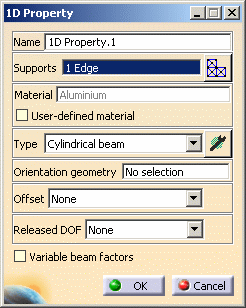
The 1D Property dialog box is updated as shown
here:
 |
-
Select Rectangular beam as Section
option.
-
Click the Component Edition button
 in the 1D Property dialog box to define dimensions.
|
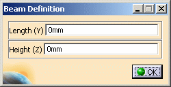
The Beam Definition dialog box appears.
 |
-
Enter 10 mm in the Length (Y)
field and 10 mm in the Height (Z) field.
-
Click OK in the Beam Definition dialog box.
|
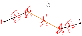
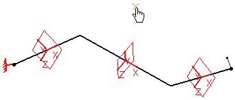
Symbols appear on the geometry to simulate the
section of the beam.
 |
-
Activate the Orientation Geometry field and
select a point.
|
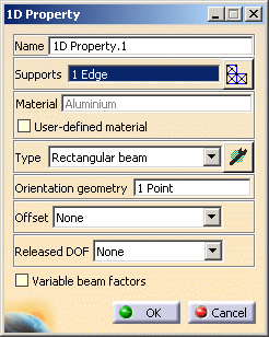
The 1D Property dialog box appears as shown here:
 |
-
Click OK in the 1D Property dialog box.
|
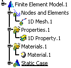
The 1D Property is added. In this case, 1D
Prorperty.1 feature appears in the specification tree.
 |
|
|

|
| |
Creating Local 1D
Property
You can associate a local section to a piece of the
geometry on the condition a 1D property was previously applied to the
geometry. |
 |
Only available with the ELFINI Structural Analysis
(EST) product. |
 |
-
Right-click the 1D Property.1 property
previously created in the specification tree and select Local 1D
Property
 . .
|
The Local 1D Property dialog box appears.
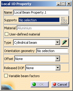
For details about the dialog box options, refer to
Adding 1D Properties.
- Name: lets you modify the name of the property.
- Supports: lets you select a support.
- Select Mesh Parts: this button is only available
if you have selected a support.
For more details, refer to Selecting
Mesh Parts.
- Material: indicates you that a material has been
applied.
- User Defined Material: lets you select an user
isotropic material on condition that it has been previously
created.
For more details, refer to Creating an
User Material.
- Type: lets you choose the type of section (and
symbol) and define the parameters.
For more details, refer to
1D Property Section Type.
- Orientation geometry: you can select point,
line or surface to orient the section of a beam.
- Offset: lets you define or not offset values at
each end of the beam.
- Released DOF: lets you release or not the degrees
of freedom.
- Variable beam factors: lets you create a linear
approximation of variable cross section beams.
|
-
Select the part of the geometry on which you want to
apply a local 1D property.
|
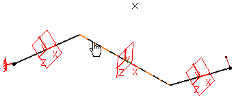
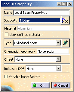
The Local 1D Property is updated as shown here:
 |
-
Change the Type option. In this particular
case, select the Thin box beam option.
|
The geometry appears as shown here:
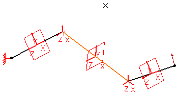
|
-
Click the Component Edition button
 in the Local 1D Property dialog box to define the dimensions of the
section.
|
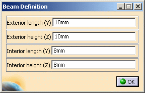
The Beam Definition dialog box appears. |
-
Enter the following values in the different fields of
the Beam Definition dialog box.
-
Click OK in the Beam Definition dialog box.
-
Select a point as Orientation Geometry.
-
Click OK in the Local 1D Property dialog
box.
|
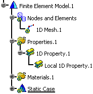
A Local 1D Property.1 property appears
in the specification tree (under 1D Property.1).
|
|
|

|
 |
Note that you can manually edit or delete 1D properties.
|


