Creating 1D Mesh Parts

This task shows you how to add beam mesh to a Generative Shape Design CATPart.

This command is available both in the Generative Structural Analysis workbench and in the Advanced Meshing Tools workbench.

  • You cannot select a sketch geometry.

  • You cannot mesh 1D body belonging to hybrid body.


Generative Structural Analysis Workbench

Top

  1. Click Beam Mesher in the Model Manager toolbar.

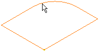
  2. Select the beam to be meshed.

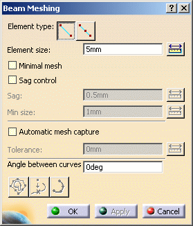
    The Beam Meshing dialog box appears.

    • Element type: lets you choose the 1D element type:
      • (linear): 1D element without intermediate node.
        By default, this element is a beam but you can work with linear bar element using the Change Element Type contextual menu.
        For more details about these elements, refer to Beam and Linear Bar in the Finite Element Reference Guide.
      • (parabolic): 1D element with an intermediate node.
        This element can only be a parabolic bar. For more details about this element, refer to Parabolic Bar in the Finite Element Reference Guide.
    • Element size: lets you specify the element size.
    • Minimal mesh: lets you use the minimal 1D mesh method. This method generates only one element between support vertices, captured nodes or isolated points for any specified mesh size.
    • Sag control: lets you control the sag. This option is not available if the Minimal mesh check box is selected.
      • Sag: lets you define the distance between the mesh elements and the geometry.
      • Min size: lets you define the minimum element size.
  3. Select the desired Element Type.

    In this particular example, click the button to select linear as element type.

  4. Enter the desired Element size value in the Beam Meshing dialog box.

    In this particular case, enter 3mm.

  5. Activate the Sag control option in the Beam Meshing dialog box.
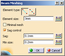
  6. Modify the Sag control parameters if needed.

  7. Click OK in the Beam Meshing dialog box.

    The 1D Mesh.2 feature now appears in the specification tree. Note that now the corresponding Beam Property is missing.
    For more details on how to add this Beam Property, refer to Creating Beam Property in the Generative Structural Analysis User's Guide.

  • To apply a restraint, a load or a connection to one extremity of a beam, you need to first put the point that were possibly created at the extremity of this beam, in order to build the wireframe, into the Hide mode. As result, to apply the above mentioned specifications, you will select the extremity of the wireframe and not the hidden point (small cross in the 3D view) as this point is not linked to the mesh.
  • You cannot apply beam properties and 1D mesh parts on geometry included in a sketch.
1D or beam mesh can be deleted and/or added to parts manually.


Advanced Meshing Tools Workbench

Top

This task shows you how to add beam mesh to a Generative Shape Design CATPart, and if needed, edit the mesh.
You can add a beam mesh on a Structure Design beam. So you will mesh it with 1D elements.

This functionality is only available with the FEM Surface (FMS) product.

  1. Click Beam Mesher in the Meshing Methods toolbar.

  2. Select the feature corresponding to the geometry to be associated a mesh part.

    The Beam Meshing dialog box appears.

    • Element type: lets you choose the 1D element type
      • (linear): 1D element without intermediate node.
      • (parabolic): 1D element with an intermediate node.
    • Element size: lets you set the global mesh size.
      The Element size value must be strictly positive.
    • Minimal mesh: lets you use the minimal 1D mesh method. This method generates only one element between support vertices, captured nodes or isolated points for any specified mesh size.
    • Sag control: lets you set the element minimum size and sag. This option is not available if the Minimal mesh check box is selected.
      The sag is the distance between the mesh elements and the geometry so that mesh refining is optimum in curve-type geometry.
    • Automatic mesh capture: lets you capture external mesh with a given tolerance (external mesh must be a 2D mesh).
      • Mesh capture button: for more details, click here.

        This button is only available if you activated the Automatic mesh capture option.

      • Tolerance: lets you enter a tolerance value.
    • Angle between  curves: lets you define the vertices to be taken into account.
    • Edit mesh button: lets you edit mesh manually to enhance quality using the Edit Mesh dialog box.
      For more details about this button and the Edit Mesh dialog box, click here.

      This button is available as soon as the mesh is generated (after clicking the Apply button).

    • Add/remove isolated points button: lets you select points to be projected on the geometry.

      This button is available as soon as a geometry has been selected.

      The External Points dialog box appears.

    • Add Mesh Distribution button: lets you specify local nodes distribution.
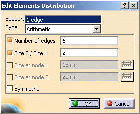
      When clicking this button, the Edit Elements Distribution dialog box appears. You can choose between several distribution types: uniform, arithmetic, geometric, user-defined law.
      For more details about the Edit Elements Distribution dialog box, refer to Distributing Elements in the Advanced Meshing Tools User's Guide.
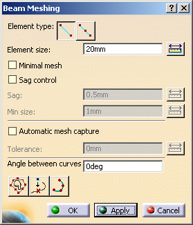
  3. Enter the desired Element size value in the Beam Meshing dialog box.

    In this example, enter 20mm as Element size value.

  4. Click Apply in the Beam Meshing dialog box to launch computation.

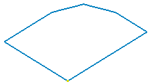
    The mesh is displayed.

    To visualize 1D elements, you can use the Shrink Elements command.

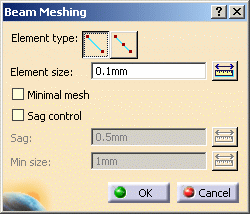
    The Beam Meshing dialog box now appears as shown here.

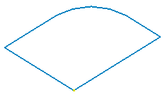
  5. Select Linear or Parabolic as Element Type option and click Apply in the Beam Meshing dialog box.

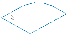
    Linear option activated

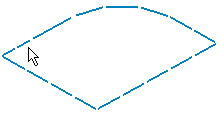
    Parabolic option activated

  6. Click OK.

    A 1D Mesh.1 feature appears in the specification tree.

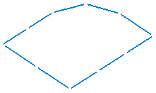
  7. Shrink the 1D element visualization.

    To do this, click Shrink Elements in the Mesh Visualization Tools toolbar and set the value of 1D elements shrink to 0.90 using the slider.
    The 1D mesh appears as shown below:

  8. Double-click 1D Mesh.1 in the specification tree and click Apply in the Beam Meshing dialog box.

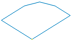
  9. Select the Sag control check box and modify the Min size and Sag values so that the mesh is refined as desired.

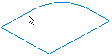
    Selected Size and Sag values

    Resulting mesh

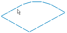
    Selected Size and Sag values

    Resulting mesh

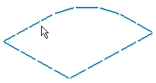
    Selected Size and Sag values

    Resulting mesh

  10. Click the Edit mesh button in the Beam Meshing dialog box.

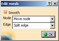
    The Edit Mesh dialog box appears.

    • Smooth: the neighbor elements are smoothed around the modified mesh.
    • Node
      • Move node: move a node belong the geometry.
      • Freeze node: fix a node whatever the modifications applied to the neighbor elements.
      • Unfreeze node: cancel the Freeze node option.
    • Edge:
      • Split edge: create a node and split an edge into two edges.
      • Condense edge: suppress an edge by condensation of one node and the node opposite to the point on the selected edge.

    Moving a node:

  11. Select the Move node option in the Node list.

  12. Select a node and move it to the desired location.

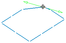
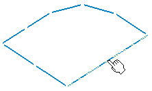
    Select the node

    Move the node

    The result is:

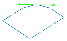
    Smooth option deactivated

    Smooth option activated

    Splitting an edge:

  13. Select the Split edge option in the Edge list.

    To refine the mesh, you need to check the Smooth option in the Edit Mesh dialog box. The neighbor edges are updated.

  14. Select the edge you want to split.

    The result is:

    Smooth option deactivated

    Smooth option activated

  15. Click OK in the Edit Mesh dialog box.

  16. Click the Add Mesh Distribution button.

    The Edit Elements Distribution dialog box appears.

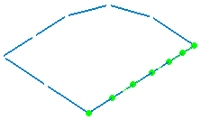
  17. Select the edge on which you want to distribute nodes.

    In this particular example, select the following edge:

  18. Set the parameters in the Edit Elements Distribution dialog box.

    In this particular example:

    The distribution is displayed:

  19. Click OK in the Edit Elements Distribution dialog box.

  20. Click Apply and then OK in the Beam Meshing dialog box.

    A Mesh Specifications.1 set containing the Elements Distribution.1 specification appears in the specification tree under the 1D  Mesh.1 mesh part.

1D (beam mesh), can be deleted and/or added to parts manually.