This task shows you how to create a Bearing Load applied to a selected geometry.
Bearing Loads are simulated contact loads applied to cylindrical parts.
Creating Bearing Loads is done in only one step and is much quicker than creating first a virtual part and then a load. Computation is also much less time-consuming, because Bearing Loads do not generate either costly contact beam elements or virtual mesh parts.
You have to select a cylindrical boundary of the part. Any type of revolution surface can be selected. You also have to specify the resulting contact force (direction and norm). The components of the force can be given either in the global or in a user axis system (similar to the Distributed Force).
Bearing loads are flexible: you can vary the angle sector on which the force is applied as well as the type of the profile distribution.
Display of the applied sinusoidal traction:
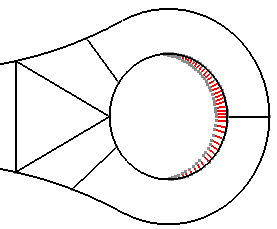
Bearing Loads objects belong to Loads sets.
Only available with the ELFINI Structural Analysis (EST) product.
Bearing Loads can be applied to the following types of supports:
|
Geometrical Feature |
Mechanical Feature |
Analysis Feature |
||||
|
Spatial Groups |
Geometrical Groups |
Groups by Neighborhood |
Groups by Boundary |
Others |
||
|
Cylindrical surface |
||||||
To know more, refer to Authorized Supports.
Open the sample02.CATAnalysis document from the samples directory.
-
Go to View > Render Style > Customize View and make sure the Shading, Outlines and Materials options are active in the Custom View Modes dialog box.
-
Click Bearing Load
 in the Loads toolbar.
The Bearing Load dialog box appears.
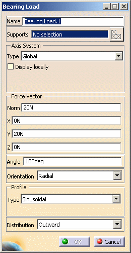
- Name: lets you modify the name of the load.
- Supports: lets you select cylindrical surfaces on which
you want to apply a bearing load.
Multi-selection is available.
Multi-selection must be used on different cylindrical surfaces and not on different elements belonging to a same cylindrical surface.
Indeed, if you apply a 10N norm force vector on a multi-selection of three surfaces belonging to the same geometry, the norm of the global resultant force will be equal to 30N (and not 10N).To apply a 10N norm force vector on three different cylindrical surfaces, the following methods are equivalent:
- create three bearing loads (select one cylindrical surface for each bearing load) with a 10N norm force vector
- create one bearing load (multi-select three cylindrical surfaces) with a 10N norm force vector
As soon as the support is selected, the Select Mesh Part button is available.
To know more about the Select Mesh Part button, refer to Selecting Mesh Parts.
- Axis System Type: allows you to choose between
Global and User Axis systems, for entering components
of the resultant force vector.
- Global: if you select the Global Axis system, the components of the resultant force vector will be interpreted as relative to the fixed global rectangular coordinate system.
- User: if you select a User Axis
system, the components of the resultant force vector will be interpreted
as relative to the specified rectangular coordinate system.
To select a User Axis system, you must activate an existing Axis by clicking it in the specification tree. Its name will then be automatically displayed in the Current Axis field.
Only the Force vector component which is perpendicular to the revolution axis is taken into account because this component is a contact component.
- Force Vector: lets you enter the three coordinates of the force vector (X, Y, Z).
- Angle: corresponds to the angle over which the forces
can be distributed. When entering an angle value, a highly precise
preview automatically appears on the model.
180 is the default value, < 180 is useful to take into account some positive clearance, > 180 is useful to take into account some negative clearance. - Orientation: provides you with two ways for distributing
forces:
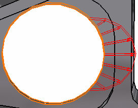
- Radial: all the force vectors at the mesh nodes are normal to the surface in all points. This is generally used for force contact.
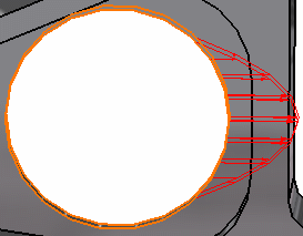
- Parallel: all the force vectors at the mesh nodes are parallel to the resulting force vectors. This can useful in the case of specific loads.
Radial:
Parallel:
- Profile: can be Sinusoidal, Parabolic
or Law type, defining how you will vary the Force intensity
according to the angle: Sinusoidal, Parabolic or Law.
- Law: or F=f(Θ)
requires that a formal law (Formal parameters) was defined in Knowledge
Advisor (Fog). On the condition you previously activated the
Show relations option in Tools > Options > Analysis
and Simulation (General tab) command, you can see
the Law feature in the specification tree. No sooner do you select
this feature in the specification tree, that this formal parameter
appears in the Law field (Bearing Load dialog box).


The law indicates the force repartition (vector norm) but it does not influence the force orientation.
The force orientation is given by the Force Vector components and the Distribution option.
- Law: or F=f(Θ)
requires that a formal law (Formal parameters) was defined in Knowledge
Advisor (Fog). On the condition you previously activated the
Show relations option in Tools > Options > Analysis
and Simulation (General tab) command, you can see
the Law feature in the specification tree. No sooner do you select
this feature in the specification tree, that this formal parameter
appears in the Law field (Bearing Load dialog box).
- Distribution: lets you specify the force distribution.
-
Outward:

B pushes on A
In this particular example, the result is the following:

-
Inward:
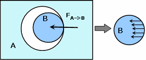
A pushes on B
In this particular example, the result is the following:
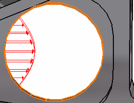
-
-
You can change the identifier of the Bearing Load by editing the Name field.
-
Select Global as Axis System Type.
-
Enter values for the X, Y, Z components of the resultant force vector.
For example, enter -500N as X value.The corresponding Norm value is automatically computed and displayed.

- You can define the resultant force vector direction by using the compass.
- By applying the compass to any part geometry, you can align the compass directions with the implicit axis directions of that geometry: drag the compass by handling the red square and drop it on the appropriate surface. The normal direction to this surface defines the new direction. Then, click on the Compass Direction button to take this new direction into account. You can now invert the direction if desired, editing the values of the three components.
-
Enter a value for the Angle parameter. For example, enter 90deg as Angle value.
-
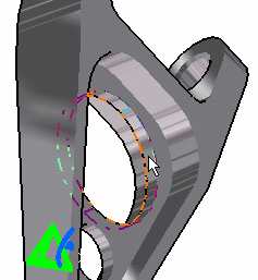
Select the support (a geometry) on which the resultant Bearing Load vectors are applied.
Any selectable geometry is highlighted when you pass the cursor over it.
Selected support:
Resultant load:
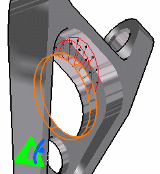
-
Select the following options:
- Radial as Orientation option
- Parabolic as Profile Type option
- Outward as Distribution option.
-
Click OK.
A Bearing Load object appears in the specification tree under the active Loads objects set.
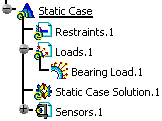
- You can either select the support and then set the Bearing Load specifications, or set the Bearing Load specifications and then select the support.
- Loads are required for Stress Analysis computations.
- If several Analysis Cases have been defined in the Finite Element Model, you must activate a Loads objects set in the specification tree before creating a Bearing Load object.
- Bearing Load objects can be edited by a double click on the corresponding object or icon in the specification tree.
Make sure the computation is finished before starting any of the following operations.
The ELFINI Structural Analysis product offers the following additional functionalities:
- Contextual menu on the load object:
- Bearing Load Visualization on Mesh: the translation of
the load specifications into solver specifications can be visualized symbolically
at the impacted mesh nodes, provided the mesh has been previously generated
using a mesh only computation.
To know more, refer to Visualizing Loads on Mesh.
- Bearing Load Visualization on Mesh: the translation of
the load specifications into solver specifications can be visualized symbolically
at the impacted mesh nodes, provided the mesh has been previously generated
using a mesh only computation.
- Contextual menus on the Loads set:
- Generate Image: generates an image of the computed loads
(along with translating all user-defined load specifications into explicit
solver commands on mesh entities), by generating symbols for the elementary
loads imposed by the loads sets. The image can be edited to include part
or all of the options available.
To know more, refer to Generating Images. - Report: the partial status and results of intermediate
pre-processor computations are reported in HTML format. It represents
a subset of the global report capability and generates a partial report
of the loads set computation.
To know more, refer to Generating Reports.
- Generate Image: generates an image of the computed loads
(along with translating all user-defined load specifications into explicit
solver commands on mesh entities), by generating symbols for the elementary
loads imposed by the loads sets. The image can be edited to include part
or all of the options available.
- Self-balancing: you can double-click the Loads
set to automatically add inertia forces in order to counter balance external
loads.
Double-click the Loads set to display the Loads dialog box that lets you choose whether you wish to apply self-balancing to the load. Example of use: if this option is used with iso-static specifications, it will allow you to simulate free-body loading. If you make the option active, the center of inertia results null.
To know more, refer to Creating Pressures.
![]()