This task shows how to visualize preprocessing specifications (Restraints, Masses, Loads) on mesh image.
The translation of preprocessing specifications into solver specifications can be visualized symbolically at the impacted mesh nodes, provided the mesh has been previously generated using a mesh only computation.
Open the sample14_1.CATAnalysis document from the samples directory.
- Select View > Render Style > Customize View and make sure the Edges points, Shading and Materials option are active in the Custom View Modes dialog box.
- Compute the mesh and the preprocessing specifications.
To do this, click Compute ,
select Mesh Only and click OK.
Visualizing Restraints on Mesh
-
Set the first static case as the current one.
To do this, refer to Changing a Current Analysis Case.
-
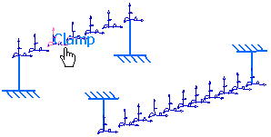
Right-click Clamp.1 in the specification tree and select Restraint Visualization on Mesh
 .
.Both the mesh and the restraint are visualized:

Two images are generated in the specification tree:
-
Mesh.1 image under the Nodes and Elements set
-
Degrees of freedom symbol.1 under the Clamp.1 restraint.
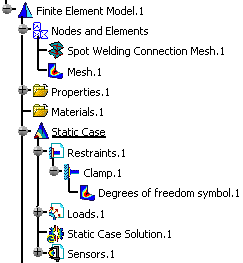
If you want to visualize only the restraint symbol, deactivate the Mesh.1 image.
-
You can access the:
-
Report contextual menu
-
Image Edition functionality
Visualizing Loads on Mesh
Open the sample14_1.CATAnalysis document from the samples directory.
- Select View > Render Style > Customize View and make sure the Edges points, Shading and Materials option are active in the Custom View Modes dialog box.
- Set the second static case as the current one.
For more details, refer to Changing a Current Analysis Case. - Compute the mesh and the preprocessing specifications.
To do this, click Compute ,
select Mesh Only and click OK.
-
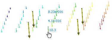
Right-click Distributed Force.1 in the specification tree and select Distributed Force Visualization on Mesh.
Both the mesh and the load are visualized:

Two images are generated in the specification tree:
-
Mesh.1 image under the Nodes and Elements set
-
Point force vector.1 under the Distributed Force.1 load.
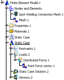
If you want to visualize only the load symbol, deactivate the Mesh.1 image.
-
-
Double-click the Deformed Mesh object in the specification tree to edit the image.
Visualizing Masses on Mesh
Open the sample14_1.CATAnalysis document from the samples directory.
- Select View > Render Style > Customize View and make sure the Edges points, Shading and Materials option are active in the Custom View Modes dialog box.
- Set the first frequency case as the current one.
For more details, refer to Changing a Current Analysis Case. - Compute the mesh and the preprocessing specifications.
To do this, click Compute ,
select Mesh Only and click OK.
-
Right-click a preprocessing set in the specification tree and select Visu on Mesh.
Both the mesh and the load are visualized:

Two images are generated in the specification tree:
-
Mesh.1 image under the Nodes and Elements set
-
Surface mass symbol.1 under the Distributed Force.1 load.
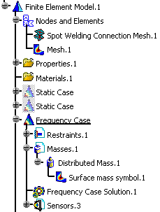
If you want to visualize only the load symbol, deactivate the Mesh.1 image.

-
-
Double-click the Deformed Mesh object in the specification tree to edit the image.
The Image Edition dialog box appears.
For more details, refer to Image Edition. -
Click OK in the Image Edition dialog box.
The image corresponding to the settings you defined is now visualized.
![]()