

3D PLM Enterprise Architecture |
3D Visualization |
Visualizing Temporary ComponentsHow to use the Interactive Set of Objects |
| Use Case | ||
AbstractA temporary component is a component which is not integrated into the data model of a V5 document. In most cases it is a simple component to help the understanding of an interactive command. The CAAVisTemporaryObjects use case [1] has explained how to create temporary components, the current one details how to use the interactive Set of Objects to visualize them. To take full advantage of this article, you can first read the technical article about the Interactive Set of Objects and the temporary components [2]. |
The main goal of this article is to show how to use the Interactive Set of Objects. The ISO enables you to visualize the temporary components, those not included in a V5 document. These components must implement either CATI2DGeoVisu or CATI3DGeoVisu.
The ISO is a CATISO class instance which is associated with the editor (CATFrmEditor) of each V5 document. There are three kinds of ISO: normal, furtive (XOR drawing) and background. The first two are used in this use case.
Naturally, you will learn how to use the methods of the CATISO class to display or erase a component, but this article goes beyond to explain the life cycle of the graphic representation associated with the components.
[Top]
CAADegClippingByBoxCmd is a use case of the CAADialogEngine.edu and CAAVisualization.edu frameworks that illustrates DialogEngine, ApplicationFrame, and Visualization frameworks capabilities.
[Top]
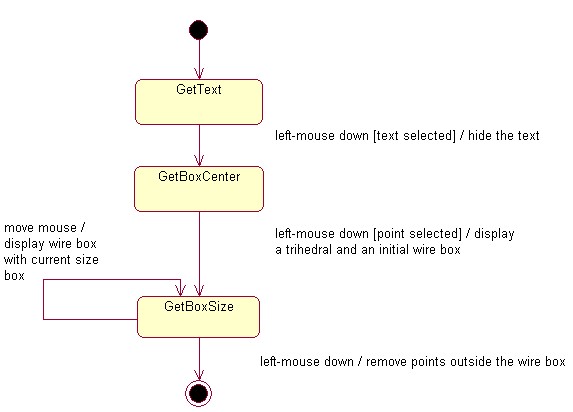
The CAADegClippingByBoxCmd use case is a state command [3] which displays temporary components to enhance the user interface. This command is a state command to remove all the points of the document outside a given box. This clipping box is defined by the end user: first, he/she defines its location by selecting an existing point. Then, from the selected point a first wire box is displayed, and he/she can drag the mouse to increase or decrease the size of the box.
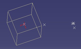
The state command creates three kinds of components: a text (right picture on Fig.1), a trihedral (middle picture on Fig.1) and a wire box (left picture on Fig.1) [1] and uses the ISO to visualize them. The first two are visualized in the normal ISO, and the last one in the furtive ISO.
 |
 |
 |
The text is displayed when the command is activated. It is useless for the result of the command itself, it has been added to show how select a temporary component.
Here it is the UML diagram [4] of the CAADegClippingByBoxCmd command.
 |
[Top]
See the section entitled "How to Launch the CAAGeometry Use Case" in the "The CAAGeometry Sample" use case for a detailed description of how this use case should be launched. For the specific scenario:
Launch CATIA. When the application is ready:
After the selection, the text disappears
After the selection, the trihedral is displayed.
All points outside the clipping box are removed from the document.
[Top]
The CAADegClippingByBoxCmd use case is made of the single class named CAADegClippingByBoxCmd located in the CAADegGeoCommands.m module of the CAADialogEngine.edu framework:
| Windows | InstallRootDirectory\CAADialogEngine.edu\CAADegGeoCommands.m\ |
| Unix | InstallRootDirectory/CAADialogEngine.edu/CAADegGeoCommands.m/ |
where InstallRootDirectory is the directory where the CAA CD-ROM
is installed.
[Top]
There are seven main logical steps in CAADegClippingByBoxCmd:
[Top]
The interactive set of objects are managed by the CATFrmEditor class [5]. In the CAADegClippingByBoxCmd class constructor they are retrieved.
... CATFrmEditor * pEditor = GetEditor(); ... _pFurtiveISO = pEditor->GetFurtiveISO() ; _pISO = pEditor->GetISO() ; ... |
The GetEditor method of the CATStateCommand class,
retrieves the current CATFrmEditor class instance. The GetISO method
retrieves the "normal" ISO, and the GetFurtiveISO method
the furtive ISO. _pISO and _pFurtiveISO are data
members of the state command.
[Top]
In the CAADegClippingByBoxCmd class constructor you will find the three creations.
...
  _pCenterBoxModel     = new CATModelForRep3D();

  ::CATInstantiateComponent("CAAVisWireBox",IID_CAAIVisWireBox,(void**)&_pIWireBox);

  ::CATInstantiateComponent("CAAVisTextModel",IID_CAAIVisTextModel,(void**)&_pITextToSelectModel);
...
|
_pCenterBoxModel, _pIWireBox, and _pITextToSelectModel
are data members of the CAADegClippingByBoxCmd class. The first one is
an instance of the trihedral component, the second one is an instance of the
wire box component, and the last one is an instance of the text component. The
referenced article [1] gives you the UML diagram of
each one.
[Top]
The CAADegClippingByBoxCmd class is a state command class. It implies that
the state chart is defined in the BuildGraph method of the CATStateCommand
class. Here it is an extract which shows the more interesting steps.
...
_daIndication = new CATIndicationAgent("Indication");

_daIndication->SetBehavior(CATDlgEngWithPrevaluation | CATDlgEngAcceptOnPrevaluate |
	                         CATDlgEngWithUndo);
|
_daIndication is a CATIndicationAgent class instance kept
as data member by the CAADegClippingByBoxCmd class. The CATDlgEngWithOnPrevaluation
behavior enables us to be informed at each mouse movement, and consequently to
increase or decrease the size of the clipping box. See the Managing
Wire Box Component step.
...
  _daTextSel = new CATPathElementAgent("SelText");
  _daTextSel->SetBehavior(CATDlgEngWithPSO | CATDlgEngWithPrevaluation);
  _daTextSel->AddElementType(IID_CAAIVisTextModel);
...
|
_daTextSel, a CATPathElementAgent pointer, is
a data member of the CAADegClippingByBoxCmd class. The association of
the CATDlgEngWithPSO and CATDlgEngWithPrevaluation
behaviors enables us to have a visual feedback when an object is pre-selected
(pre-highlight
color). The AddElementType is the method to filter the selection.
Using CAAIVisTextModel, only the components implementing this interface
could be selected. This interface is only implemented on text component [1].
[Top]
The text component ("ISO Selection") is managed as follows:
Here it is the detail of the parts own to the text component.
When the state command is first activated, the text is displayed to be selected by the end user. This step consists in to create the graphic representation of the text component, and sets the component in the normal ISO.
...
   HRESULT rc = CreateRepForText();

  _pISO->AddElement(_pITextToSelectModel);
...
|
The text component, _pITextToSelectModel, is
created at the Creating the Three Temporary Components
step.
The CreateRepForText method creates the graphic representation
and associates it with the component. Refer for details to the "Creating
Graphic Representation" sub-step of the "Creating
the Text Component" step of the referenced article [1].
The component can be now visualized. The AddElement method adds the
component, handled by _pITextToSelectModel, in the normal ISO.
This method will send a CATCreate event to update the visualization.
Refer to the technical article [2] for details.
The text has been selected, it must be erased.
... _pISO->RemoveElement(_pITextToSelectModel,1) ; ... |
The RemoveElement method removes the component,_pITextToSelectModel,
from the ISO. This method will send a notification to update the
visualization. The last argument is important. The value 1 means
that the graphic representation associated with the component will be not
deleted. So, you could re-add the component into the ISO without re-create the graphic
representation. See the next step.
It is the Undo/Redo of the action which consists in to select the text. The Undo action re-displays the text, whereas the Redo action, erases back the text.
Undo cases:
... _pISO->AddElement(_pITextToSelectModel); ... |
Redo cases:
... _pISO->RemoveElement(_pITextToSelectModel,1); ... |
You can note that the since the _pITextToSelectModel component
is always removed from the ISO without the destruction of its graphic
representation, thanks the value 1 for the last argument of the RemoveElement
method, there is no need to re-create the graphic representation into the undo
action method.
A state command can be deactivated by a shared command, and once this command is completed, our command is reactivated [6]. The management of the text component, in this case, follows the same principle as into the undo/redo methods. When the command is deactivated the text is erased without its graphic representation destruction. So in case of re-activation of the state command, the text can be re-displayed without graphic representation reconstruction.
However, there is a little difference with the undo/redo step. In the Deactivation method, a check of the presence into the ISO of the text is done, it enables us in the re-activation method to avoid to re-display the text if it useless.
Extract of the
Desactivatemethod of the CAADegClippingByBoxCmd command:
...
if ( _pISO->IsMember(_pITextToSelectModel) )
{
   _pISO->RemoveElement(_pITextToSelectModel,1);
   _TextModelToRestore = TRUE ;
}
...
The
IsMembermethod enables us to keep the state of the text._TextModelToRestore, a boolean value, will be then used in theActivatemethod.Extract of the
Activatemethod of the CAADegClippingByBoxCmd command:
...
if ( TRUE == TextModelToRestore  )
{
   _pISO->AddElement(_pITextToSelectModel);
}
...
The text is added in the ISO only if before the de-activation the text was displayed. You can note that there is no need to re-build the graphic representation of the
_pITextToSelectModelcomponent since in the deactivation method the last argument of theRemoveElementmethod is1.
[Top]
The trihedral component is managed as follows:
Here it is the detail of the parts own to the trihedral component.
When the end user has selected a point to specify the center of the clipping box, a trihedral is displayed. This step consists in to create the graphic representation of the trihedral component, and sets the component in the normal ISO.
...
rc = CreateRepForCenterBox();

_pISO->AddElement(_pCenterBoxModel);
...
|
The trihedral component, _pCenterBoxModel, is
created at the Creating the Three Temporary Components
step.
The CreateRepForCenterBox method creates the graphic representation
and associates it with the component. Refer for details to the "Creating
the Trihedral Component" step of the referenced article [1].
The component can be now visualized. The AddElement method adds the
component, handled by _pCenterBoxModel, in the normal ISO.
This method will send a CATCreate event to update the visualization.
Refer to the technical article [2] for details.
When the state command is deactivated, the trihedral component must be erased. Here it is an extract of the
Desactivatemethod of the CAADegClippingByBoxCmd command:
...
if ( _pISO->IsMember(_pCenterBoxModel) )
{
   _pISO->RemoveElement(_pCenterBoxModel,0);

   _CenterBoxModelToRestore = TRUE ;
}
...
|
The trihedral component, _pCenterBoxModel, is
created at the Creating the Three Temporary Components
step.
The IsMember method enables us to valuate a boolean data
member, _CenterBoxModelToRestore , which will be used in the Activate
method. It is the only one interest of this call because the RemoveElement
method checks that the component exists in the ISO. Note that the last
argument of this method is 0, the default value. Its means that the graphic
representation of the trihedral component is deleted by the removal operation.
Now, an extract of the Activate method:
...
if (TRUE == _CenterBoxModelToRestore)
{
   HRESULT rc = CreateRepForCenterBox();

   _pISO->AddElement(_pCenterBoxModel);

...
|
The trihedral component, _pCenterBoxModel, is re-displayed
only if it was drawn before the deactivation ( test on _CenterBoxModelToRestore).
Before to add the component into the ISO, you must re-create the graphic
representation because in the de-activation step it has been deleted by the RemoveElement call.
[Top]
The wire box component is managed as follows:
Here it is the detail of the parts own to the wire box component.
Once the point representing the center of the clipping box has been selected, a first wire box is drawn.
... _pIWireBox->SetCenterBox(_CenterBox); _pIWireBox->SetDimBox(.2f); _PreviousPointInScreenPlane = _daIndication->GetValue(); _pFurtiveISO->AddElement(_pIWireBox); ... |
_pIWireBox is a CAAIVisWireBox interface pointer on the
wire box component created in the class constructor. Refer to the Creating the Three
Temporary Components step for details about the _pIWireBox
data member.
The CAAIVisWireBox interface, an interface implemented by the wire
box component [1], enables us to initialize the value of
the wire box. SetCenterBox sets the position of the selected
point, _CenterBox, on the component, and .2 is the
initial size of the box.
_PreviousPointInScreenPlane keeps the current position of the
mouse. _daIndication is an agent of indication, see the Defining the State Chart Diagram
step.
_pFurtiveISO is the furtive ISO associated with the editor of
the document. See the Retrieving the
Normal and Furtive ISO step which explains how to retrieve it.
Then, the component is set into the ISO to be displayed. The AddElement method adds the
component, handled by _pIWireBox , in the furtive ISO.
This method will send a CATCreate event to update the visualization.
The CATVisManager [7] will invoke the build
method of the CATI3DGeoVisu interface implemented by the wire box. Refer for details to the "Implementing
CATI3DGeoVisu Interface" sub-step of the "Creating
the Wire Box Component" step of the referenced article [1].
At each mouse movement, the UpdateClippingBox method is
called.
...
CATMathPoint2D CurrentPointInScreenPlane = _daIndication->GetValue();
float currentdimbox = .2f;
_pIWireBox->GetDimBox(¤tdimbox);
if ( CurrentPointInScreenPlane.GetY() > _PreviousPointInScreenPlane.GetY() )
{
currentdimbox += .05f ;
}else
{
if ( (currentdimbox - .2f) > EPSILON )
{
currentdimbox -= 0.05f ;
}
}
_PreviousPointInScreenPlane = CurrentPointInScreenPlane ;
...
|
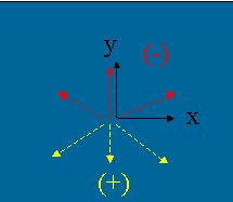
The first step of this method consists in to define if the size of the box increases or decreases. The following rule has been chosen:
 |
The black trihedral represents the axis system for the value returned
by the agent of indication ( When the mouse goes down ( the previous Y position is upper than the the current one) the wire box increases, otherwise it decreases. But there is a lower limit: the size of the box cannot be lowest that .2f unit model.
|
Once the new size of the box is defined, thanks _pIWireBox,
the CAAIVisWireBox interface pointer on the wire box component, the
component can be updated.
... _pIWireBox->SetDimBox(currentdimbox) ; ... |
There remains to update the ISO. The UpdateElement method will
send a CATModify event which implies the automatic reconstruction of the graphic
representation.
... _pFurtiveISO->UpdateElement(_pIWireBox); ... |
![]() if
you use the
if
you use the UpdateElement method you must never modify
"yourself" the graphic representation. The modification must
be managed by the CATVisManager. So it is the reason why for the wire box we
have chosen to create a component which OM derives from CATBaseUnknown and not
from CATModelForRep3D. It is in your CATI3GeoVisu implementation that the
graphic representation is built. Refer to the technical article for complete
details [2].
[Top]
At the end of the command, in the CAADegClippingByBoxCmd destructor class, the three temporary components must be removed from the ISO and then deleted.
In the Cancel method, the component are removed from the
ISO. You do not have to test if the component already exists in the ISO, the RemoveElement
method does it.
...
     _pISO->RemoveElement(_pITextToSelectModel);
     _pISO->RemoveElement(_pCenterBoxModel);

     _pFurtiveISO->RemoveElement(_pIWireBox);

...
|
_pISO and _pFurtiveISO are data members initialized
in the Retrieving the Normal
and Furtive ISO step.
In the destructor class, the component are deleted by releasing
the handles:
...
     _pITextToSelectModel->Release();

     _pCenterBoxModel->Release();

     _pIWireBox->Release();
...
|
_pITextToSelectModel, _pCenterBoxModel, and _pIWireBox
are data members initialized in the Creating the Three Temporary Components
step.
[Top]
This use case has explained how to use the main methods of the CATISO class:
AddElement to visualize a componentRemoveElement to erase a componentUpdateElement to update the graphic representation of a component already existing in
the ISO.[Top]
| Version: 1 [Fev 2004] | Document created |
| [Top] | |
Copyright © 2004, Dassault Systèmes. All rights reserved.