RADE |
C++ Interactive Dashboard |
Working with the RADE Dashboards - Part 2C++ Code generator features |
| Technical Article | ||
AbstractThis article describes how to use the Code Generator commands available in Visual Studio .NET. The Code Generator is a suite of commands designed to help you develop your own code, integrated in the V5 development platform. To compile your code, you need to use the mkmk tools described in "Principles of use - How to open and build a CAA V5 workspace" [1]. If you work with the C++ Interactive Dashboard and your environment has not been set up for V5 tools, we advise you to read Customizing Microsoft Visual Studio .NET [2] that provides information that will help you set it up and migrate a V5 Workspace to a format which can be used by Visual Studio .NET. Before using the commands available through the Code Generator, it is strongly recommended to have a clear understanding of the CAA V5 Workspace File Tree. A knowledge of V5 object modeler principles can also prove useful. |
| Even if the Code Generator commands are available, they cannot work until you open a CAA V5 workspace. If you try to use them before opening a workspace you will get an error message (see picture opposite.) |
|
In order to remedy the situation, open or create a V5 workspace. Below is a short summary explaining how to open a V5 workspace. For more information, see Principles of use - How to open and build a CAAV5 workspace.
[Top]
To open a workspace, proceed as follows:
|
 |
[Top]
The commands available in the Code Generator are a set of wizards where you specify a series of parameters. The Code Generator will generate the code for you. Before creating the code, a report window is displayed enabling you to check that the code generated is as expected.
|
|
You may find that some of the generated source files contain commented out statements such as "DO NOT EDIT :: THE CAA2 WIZARDS WILL INSERT CODE HERE". Do not modify what you find between these commented lines or the wizards will no longer be able to insert code in the source file. |
[Top]
Code Generator commands enable you to create the necessary V5 directory structure. The wizard will assist you in creating new frameworks and modules using the available tools. You can then start populating your directories either by using the available wizards, or by creating new objects, using Visual Studio .NET.
[Top]
To create a framework, proceed as follows:
|
 |
The wizard creates the following directory structure:
Education type frameworks are suffixed ".edu" and Test frameworks are suffixed ".tst". The wizard appends these suffixes to the framework name.
[Top]
An interface framework is a framework that contains (mainly) interfaces in both C++ or IDL language. The structure of this interface is very specific. V5 naming conventions need these interfaces to be distinguishable through an "Interfaces" suffix. Therefore if you type in "Bird" in the framework name, the generated framework will be called "BirdInterfaces". The generated structure is the following:
After the file structure has been created, the C++ Interactive Dashboard updates your project to take the new files and directories into account. Note that the framework is set as the current active project.
[Top]
If you want to create a module, you should be in a valid framework. Make the framework your active project.
To create a new module, proceed as follows:
|
 |
|
|
The newly created module is set as the current active one. |
[Top]
Code Generator wizards enable you to create specific V5 objects that implement customary V5 patterns. These currently include:
|
|
The source code is generated in the
currently active module. If the active project is not a module, a warning
box will ask you to set your module as the active project. To set
activate the module, right-click the project in the Solution Explorer
view, and select |
 |
[Top]
To create a class, proceed as follows:
|
 |
The wizard creates a header and a source file including a standard constructor and destructor, an equal operator and a copy constructor. The following files are created.
[Top]
To create an interface, proceed as follows:
|
 |
|
|
V5 naming conventions require that your interface have a 3 letter prefix, followed by the letter 'I' in upper case, followed by anything else, as in CATINavigateObject. |
The following files are created.
[Top]
IDL interfaces can only be generated in an Interface framework. The IDL radio button will be grayed out in any other type of framework.
|
 |
[Top]
Component implementations are written in C++. They cannot be included into interface frameworks. To create a component, proceed as follows:
File menu, select
Add CAAV5 Item…->Component…. The
Insert Component window is displayed.OK.OK.
You can choose to specify interfaces to implement manually, or
by using the dialog box showing available interfaces. To generate code
correctly, we must find interfaces declarations.
If you use the dialog box showing available interfaces, the search is done when
finding all interfaces. So no search will be done when generating code.
|
|
If you add interfaces manually, when clicking
OK, the search will be launched
for each added interface. First, we try to find .h file and then we try to
find .idl files. This search is performed, by default, in the current
workspace.
If you check the |
 |
|
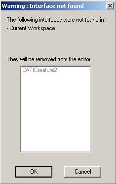
At the end of the search, a dialog box displays all the interfaces that were not found, and will suggest you to remove these interfaces. If you cancel, you can decide to remove them manually, or to check existence in the prerequisite workspaces (if you didn't select it before).
|
 |
|
|
Even though you can create an
implementation from either a C++ or an IDL interface, the wizard will not
work on an uncompiled IDL header. If you directly enter the name of the interface you want to implement, the command will prompt you to specify the header file that contains the definition of the interface. You may also ask the wizard for the list of all the available interfaces in your workspace, or in your prerequisite workspaces (this may take some time as it parses all the interfaces in the workspace). |
Principle graphic:
Principle graphic:
TIE: When a pointer to an interface is required, a new TIE instance is returned even if there is already one. By default, use TIE as adhesion type.
TIEchain: When a pointer to an interface is required, an existing one is returned if possible. That implies better performance, better memory usage, but needs reference counting on interfaces. You should use this type, rather than the standard TIE, when many "QueryInterface" calls to the interface are performed in the application.
When you click OK in the Insert
Component window, a CAA V5 Generation window is displayed showing you the files
that will be created (see below.)
[Top]
This command is similar to the previous one. It lets you add new extensions to already existing implementations. To add extensions, proceed as follows:
File menu, select
Add CAAV5 Item…->Component extension...
The Insert Component window is displayed.OK.OK.
The generated objects for extensions are the same as for components.
| How can I... | ||
| ... change an interface adhesion from the TIE mode to the BOA mode (for components and extensions)? | First, you cannot use BOA if you have a Code
extension. Besides, your extension must inherit from your
interface, so your extension and your interface must have the same
function signatures. As
multiple inheritance is forbidden, your extension must not already
inherit from any C++ class (except CATBaseUnknown). In the source code, just do the following changes. In the picture opposite, the class Extension implements the interface CATInterface in TIE mode, and we want to switch to the BOA mode) and check the dictionary file.
|
 |
| ...change an extension type? | Type change depends on the content of your
extension. If you want to convert a Data extension into a Code extension, you have to check if your class has no members and no interfaces adhesion in TIEchain mode. By default, all the TIEchains contained in this file will be converted
into TIE to ensure a good execution. In the source code, just do the following changes (see picture opposite): Example: DataExtension --> CodeExtension. |
 |
| ... use an adapter? |
By default, the inheritance in the Component builder implies the "ObjectModeler inheritance". But, some of you may want to derive from an adapter, to prevent from redefining all methods. The graphic below explains how to use an adapter for an interface.
|
|
You can create several different types of new commands that you can add to your workshops. To do so, proceed as follows:
|
 |
[Top]
You can create interactively a new dialog element based on the Dialog framework. To do so, proceed as follows:
From the File menu, select
Add CAAV5 Item->CATIA Resource->Dialog....
When you select this command, a new page is inserted into your MsDev environment with a new and empty dialog. To find out more, see Dialog builder features.
[Top]
You can create interactively a new test case script inside a test-dedicated framework. To do so, proceed as follows:
File menu, select
Add CAAV5 Item->Test-Case... The
Insert Test Case dialog box is displayed.
|
OK when done. A new test case script is created in your framework. This test case can be
run using Replay Test-Cases available
in the Tools menu.
[Top]
The component builder currently only allows you to generate one type of V5 pattern: Workshops (or workbenches). To do so, proceed as follows:
|
|
The wizard guides you through a series of
windows that prompted you to enter the characteristics of the object you
wish to create. After filling in each window, you can move on to the next
window using the wizard navigation bar. When all the steps have been
completed, click the Finish
button to generate the component.
|
Define if you want to include the Select command.
Click the ... button to add your commands and click Next>.
Click the Finish button.
[Top]
| [1] | Working with the RADE Dashboards - Part 1 |
| [2] | Customizing Microsoft Visual Studio .NET |
| [Top] | |
| Version: 1 [January 2000] | Document created |
| Version: 2 [May 2003] | Document updated |
| Version: 3 [February 2005] | Document updated |
| Version: 4 [December 2005] | Document updated |
| [Top] | |
Copyright © 2006, Dassault Systèmes. All rights reserved.