Mechanical Modeler |
Creating a Sketch on an Axis System PlaneUsing the axis system sub-elements |
|
| Use Case | ||
AbstractThis article shows how to use a sub-element of an axis system. |
An axis system is a feature whose the geometry consists in a vertex (the origin), three edges (three axes) and three planes. There are the sub-elements. This use case is intended to show you how to:
[Top]
CAAMmrAxisSystemBRep is a use case of the CAAMechanicalModeler.edu framework that illustrates MechanicalModeler framework capabilities.
[Top]
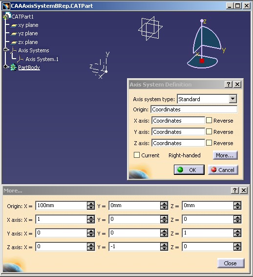
CAAMmrAxisSystemBRep creates an axis system [2], retrieves its XY plane , featurizes it and creates a sketch based on this plane.
The characteristics of the axis system are the following:
 |
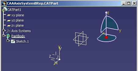
The sketch is based on the XY plane, it means in the xz plane of the absolute axis system.
 |
The above picture is a screen print of the CAAAxisSystemBRep
Part document created by the CAAMmrAxisSystemBRep use case. You find it in the CAAMechanicalModeler.edu/InputData
directory
InstallRootDirectory/CAAMechanicalModeler.edu/InputData
InstallRootDirectory\CAAMechanicalModeler.edu\InputData[Top]
To launch CAAMmrAxisSystemBRep , you will need to set up the build time environment, then compile CAAMmrAxisSystemBRep along with its prerequisites, set up the run time environment, and then execute the use case [3]. To launch the use case execute the command:
mkrun -c CAAMmrAxisSystemBRep [Filename]
where Filename is the complete file name of the output Part document. If no name is given, the Part document, named CAAMmrAxisSystemBRep, is saved in the current directory.
[Top]
The CAAMmrAxisSystemBRep use case is made of one module, CAAMmrAxisSystemBRep.m, found in the the CAAMechanicalModeler.edu framework and containing a single source program, CAAMmrTestBRep.cpp:
| Windows | InstallRootDirectory\CAAMechanicalModeler.edu\CAAMmrAxisSystemBRep.m\ |
| Unix | InstallRootDirectory/CAAMechanicalModeler.edu/CAAMmrAxisSystemBRep.m/ |
where InstallRootDirectory is the directory where the CAA CD-ROM
is installed.
[Top]
There are seven logical steps in CAAMmrAxisSystemBRep:
[Top]
CAAMmrAxisSystemBRep begins by creating a session, and creating a new Part
document. Next it retrieves the root container of this Part as a pointer to CATIPrtContainer,
pIPrtContOnDocument. This is the usual sequence for creating a Part
document [4].
[Top]
There are two factories to retrieve: the axis system and sketch factories.
The CATIMf3DAxisSystemFactory and CATISketchFactory are all
the two implemented by the root container, pIPrtContOnDocument the
specification container, of the Part document [5].
...
  CATIMf3DAxisSystemFactory * pIMf3DAxisSystemFactoryOnFeatCont = NULL ;
  rc = pIPrtContOnDocument->QueryInterface(IID_CATIMf3DAxisSystemFactory,
                                      (void **) & pIMf3DAxisSystemFactoryOnFeatCont);
  CATISketchFactory * pISketchFactoryOnFeatCont = NULL ;
  rc = pIPrtContOnDocument->QueryInterface(IID_CATISketchFactory,
                                      (void **) & pISketchFactoryOnFeatCont);
...
|
[Top]
An axis system is created thanks to the CATIMf3DAxisSystemFactory
interface. pIMf3DAxisSystemFactoryOnFeatCont is the interface
pointer on the specification container of the Part document retrieved in the
previous section. The article entitled "Creating an Axis System" [2]
explains in details the axis system creation.
Here it is a simple axis system located in (100,0,0) in the absolute axis
system and with three axis directions set by mathematical vectors. The first two
axis directions, Xdir and Ydir, are given, the third
is the vectorial product of the two firsts. NewAxisSystem is
consequently an right-handed axis system.
... CATMathPoint Origin (100.0,.0,.0); CATMathVector Xdir (1.0,0.0,.0); CATMathVector Ydir (0.0,0.0,1.0); CATIMf3DAxisSystem_var NewAxisSystem ; rc = pIMf3DAxisSystemFactoryOnFeatCont->CreateAxisSystem(Origin,Xdir,Ydir,NewAxisSystem); ... |
Once the axis system is created, an update is launched to build the geometry.
...
  CATISpecObject * pSpecObjectOnAxisSystem = NULL ;
  rc =NewAxisSystem->QueryInterface(IID_CATISpecObject,(void **)&pSpecObjectOnAxisSystem);

  CATTry
  {
     pSpecObjectOnAxisSystem->Update();
  }
  CATCatch(CATError,error)
  {
     cout<< error->GetNLSMessage().CastToCharPtr() << endl;
     Flush(error);
     return 1 ;
  }
  CATEndTry

  pSpecObjectOnAxisSystem->Release();
  pSpecObjectOnAxisSystem= NULL;
...
|
[Top]
Once the axis system has been updated, and its geometry computed, it is possible to retrieve one of its sub-element.
... CATIBRepAccess_var PlaneBRep ; rc = NewAxisSystem->GetPlaneBRepAccess(CATAxisSystemZNumber,PlaneBRep); ... |
The GetPlaneBRepAccess method retrieves a plane of the axis
system. The first argument of the method, a CATAxisSystemXYZNumber value,
specifies which. With CATAxisSystemZNumber, it is the XY plane, in
other words the plane defined by the X and the Y axis directions.
PlaneBRep is a temporary handler on the plane cell. It is an
object of selection [1] usually named a BRep object.
The CATIBRepAccess interface manages the BRep objects.
[Top]
To be used as specification, the BRep plane, PlaneBRep, should
be featurized. The new feature, MFPlane, is called the BRep
feature. The CATIFeaturize interface enables you to do this
transformation. The shape of the plane being not important, a featurization with
the functional mode is sufficient. Consequently, the FeaturizeF method is
used.
... CATIFeaturize * pIFeaturizeOnPlane = NULL ; rc = PlaneBRep->QueryInterface(IID_CATIFeaturize,(void **) &pIFeaturizeOnPlane); ... CATISpecObject_var MFPlane = pIFeaturizeOnPlane->FeaturizeF(); ... |
[Top]
The sketch is created thanks to the factory retrieved in the "Retrieves the Factory
Interface Pointers" section. MFPlane is the BRep feature
support of the sketch. [6]
... CATISpecObject_var NewSketch = pISketchFactoryOnFeatCont->CreateSketch(MFPlane); ... |
[Top]
The last actions of the use case are the following: save as the Part document, close it and delete the session. It is also described in the Creating a New Document use case [4].
[Top]
This use case explains how to create a sketch based on an axis system's plane.
[Top]
| [1] | Generic Naming |
| [2] | Creating Axis Systems |
| [3] | Building and Launching a CAA V5 Use Case |
| [4] | Creating a New Document |
| [5] | The Structure of a Part Document |
| [6] | Creating Sketching Elements in a Part Document |
| [Top] | |
| Version: 1 [Apr 2003] | Document created |
| [Top] | |
Copyright © 2003, Dassault Systèmes. All rights reserved.