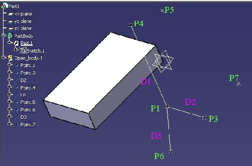
Point.1 (xy plane, H=50, V=50)
Point.3 (xy plane, H=50, V=100)
Point.4 (50,50,100)
Point.5 (0,50,100)
Point.6 (100,100,0)
Point.7 (-200,0,0)
D1 = (P1,P4)
D2 = (P1,P3)
D3 = (P1,P6)
Mechanical Modeler |
Creating Axis SystemsUsing CATIMf3DAxisSystemFactory and CATIMf3DAxisSystem |
|
| Use Case | ||
AbstractThis article shows how to use the CATIMf3DAxisSystemFactory and CATIMf3DAxisSystem interfaces to create axis systems. |
This use case is intended to show you how to create axis systems by using the CATIMf3DAxisSystemFactory and the CATIMf3DAxisSystem interfaces. You will learn to :
[Top]
CAAMmrAxisSystemCreation is a use case of the CAAMechanicalModeler.edu framework that illustrates MechanicalModeler framework capabilities.
[Top]
CAAMmrAxisSystemCreation creates several axis systems from data retrieved
inside the CAAAxisSystemCreation Part document.
|
Point.1 (xy plane, H=50, V=50)
|
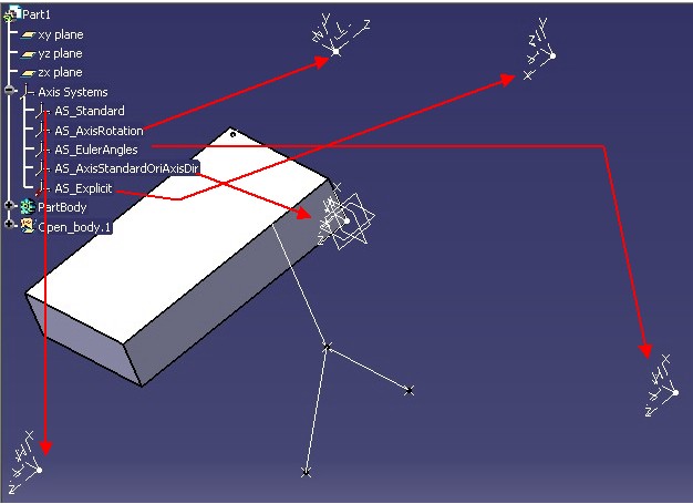
Five axis systems are created. The CAAAxisSystemCreation_Save
Part document shows them:
 |
The first axis system is a "Standard" axis system, you can verify that in the Axis System Definition dialog box just below:
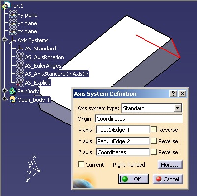 |
For a standard axis system you can propose an axis direction for the three one.
 |
The three axis directions X, Y and Z are explicitly given or can be automatically computed if no vector is specify. |
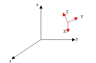
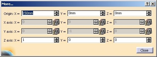
The AS_Standard's axis system characteristics are:
In the More Dialog object, you can see the internal data:
 |
In this case, you will learn how to create a standard axis system and how to use BRep features as axis direction inputs.
The second axis system is an "Axis rotation" axis system. You can verify that in the Axis System Definition dialog box just below:
 |
An "rotation axis" axis system means that you can propose one axis direction (AR) to rotate about, one specification to be the rotation's reference (Ref) and an angle of rotation (h). The schema below presents the three data in general:
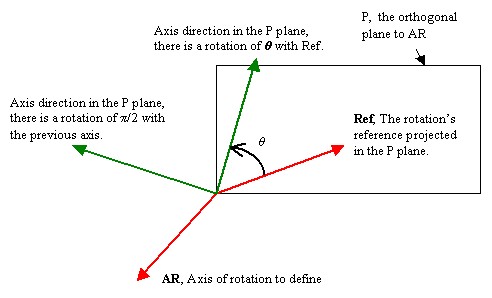 |
This schema shows the AS_AxisRotation's axis system characteristics:
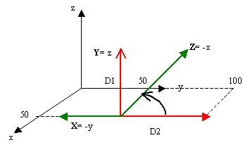 |
|
In the More Dialog object, you can see the internal data:
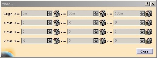 |
In this case, you will learn how to set the three data (AR, Ref and h)
and how to specify the axis direction order.
The second axis system is an "Euler angles" axis system. You can verify that in the Axis System Definition dialog box just below:
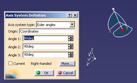 |
An "Euler angles" axis system means that you can propose three angles to form an Euler axis system. This schema presents the Euler system:
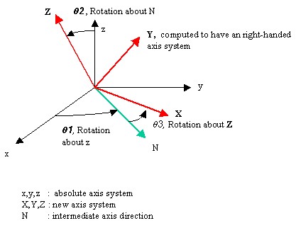 |
The vector Y is computed to have an right-handed axis system. |
The AS_EulerAngles's axis system characteristics are:
|
|
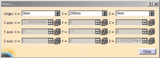
In the More Dialog object, you can see the internal data:
 |
In this case, you will learn how to set the three angles.
This axis system is created from the AS_Standard axis system. We have only changed the origin's location. The AS_AxisStandardOriAxisDir axis system is located at the axis direction's origin.
 |
You can see that the axis direction's coordinates are identical to the AS_Standard axis system. See Fig3.c
In this case, you will learn how to create an axis system from another one and how to locate it at the axis direction's origin.
The last axis system enables you to understand the creation of an explicit axis system. It means that its geometry (CATBody) will be fixed, no modification to change the origin location or the axis directions will be possible.
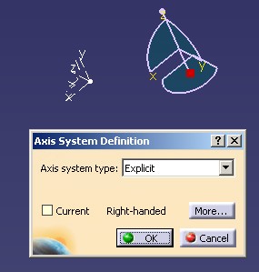 |
Before to be fixed, the AS_Explicit axis system is a standard axis system with the characteristics as follows:
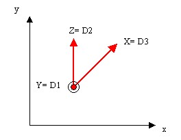 |
The three axis directions are given in this order:
|
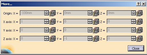
You can remark that this axis system is not orthogonal. So its internal data are automatically modified (during the update operation) to be orthonormal. The axis order determines the modifications:
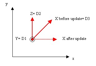 |
|
To be complete, the location of the newly axis system is the Point.7. This point is initially in (-200,0,0). It is move to (-100,0,0).
 |
[Top]
To launch CAAMmrAxisSystemCreation , you will need to set up the build time environment, then compile CAAMmrAxisSystemCreation along with its prerequisites, set up the run time environment, and then execute the use case [1]. To launch the use case execute the command:
mkrun -c CAAMmrAxisSystemCreation InputPath [OutputPath]
where
CAAAxisSystemCreation Part
document included in the directory CAAMechanicalModeler.edu/InputData
InstallRootDirectory/CAAMechanicalModeler.edu/InputData
InstallRootDirectory\CAAMechanicalModeler.edu\InputDataCAAAxisSystemCreation_Save
Part document will be saved. If this path is empty, the file will be saved
in the current directory[Top]
The CAAMmrAxisSystemCreation use case is made of several files located in the following modules of the CAAMechanicalModeler.edu framework (*)
(*)
| Windows | InstallRootDirectory\CAAMechanicalModeler.edu\ |
| Unix | InstallRootDirectory/CAAMechanicalModeler.edu/ |
where InstallRootDirectory is the directory where the CAA CD-ROM
is installed.
[Top]
There are height logical steps in CAAMmrAxisSystemCreation:
[Top]
CAAMmrAxisSystemCreation begins by creating a session, and opening the input
Part document. Next it retrieves the root container of this Part as a pointer to
CATIPrtContainer, pIPrtContOnDocument . This is the usual
sequence for loading a Part document [2].
Thanks to the GetPart method on the root container we
retrieve the Mechanical Part. This part is handled by the smart pointer spSpecObjectOnPart. This
pointer will be useful to search specifications in the document.
[Top]
The CATIMf3DAxisSystemFactory interface is implemented by the root
container, pIPrtContOnDocument, which is also the specification
container of the Part document [3].
...
  CATIMf3DAxisSystemFactory * pIMf3DAxisSystemFactoryOnFeatCont = NULL ;
  rc = pIPrtContOnDocument->QueryInterface(IID_CATIMf3DAxisSystemFactory,
                                      (void **) & pIMf3DAxisSystemFactoryOnFeatCont);
...
|
[Top]
The axis system is created by the CATIMf3DAxisSystemFactory interface. The method's creation with one point and two vectors has been chosen.
... CATMathPoint Origin (150.0,.0,.0); CATMathVector X (1.0,.0,.0); CATMathVector Y (0.0,1.0,.0); CATIMf3DAxisSystem_var NewAxisSystemStd ; rc = pIMf3DAxisSystemFactoryOnFeatCont->CreateAxisSystem(Origin,X,Y,NewAxisSystemStd); ... |
pIMf3DAxisSystemFactoryOnFeatCont is the CATIMf3DAxisSystemFactory
interface pointer on the specification container. NewAxisSystemStd
is the newly axis system. The origin is located in (150,0,0) in the absolute
axis system. The X,Y values are not important since the axis
directions will be redefined further after.
Then, Pad.1 is retrieved from the Part document thanks to the CAAMmrGetGeometry
global function. Its contents being not essential for the use case, the code is
not detailed here; refer to the source file otherwise.
... CATBaseUnknown * pPad = NULL ; rc = ::CAAMmrGetGeometry(spSpecObjectOnPart,"Pad.1",&pPad); ... |
spSpecObjectOnPart is the smart pointer on the Mechanical Part,
see the prolog section, and pPad is a CATBaseUnknown
pointer on Pad.1. Thanks to this pointer the CAAMmrRetrieveCornerAndVectorsFromPad
global function retrieves two edges coming from the same corner.
... CATBaseUnknown *pCorner = NULL; CATBaseUnknown *pVectorX = NULL; CATBaseUnknown *pVectorY = NULL; CATBaseUnknown *pVectorZ = NULL; rc=::CAAMmrRetrieveCornerAndVectorsFromPad(pPad,&pVectorX,&pVectorY); ... |
The output arguments of this function pVectorX and pVectorY
are not cells but the featurization (a BRep feature) of these cells. Here just
an extract of the global function which explains how to go from a cell to a BRep
feature.
...
 CATIGeometricalElement_var FeatureResultGeomElt = FeatureResult ;
 CATCell_var spEdgeCell = ListEdgeCorner[1] ;
 CATIBRepAccess_var BRepEdge1 = CATBRepDecode(spEdgeCell,FeatureResultGeomElt);

 CATISpecObject_var MFEdge1Cell = FCell->FeaturizeF();
 MFEdge1Cell->QueryInterface(IID_CATBaseUnknown,(void**) &(*oVectorX));
...
|
FeatureResult is the feature for which the associated
topological result (a CATBody) contains the two edges (ListEdgeCorner).
BRepEdge1 is the BRep object of the edge obtained with the CATBRepDecode
global function. This object is featurized thanks to the CATIFeaturize
interface. The FeaturizeF method is used because a functional
featurization is sufficient. oVectorX is a CATBaseUnknown
pointer, the first output argument of the global function.
![]() For
all BRep features, used to define the origin or an axis direction, a functional
featurization is sufficient.
For
all BRep features, used to define the origin or an axis direction, a functional
featurization is sufficient.
Now, that the Brep features are created, the axis directions can be defined.
... NewAxisSystemStd->SetAxisDirection(CATAxisSystemXNumber, pVectorX); NewAxisSystemStd->SetAxisDirection(CATAxisSystemYNumber, pVectorY); ... |
The SetAxisDirection method is used for the X (CATAxisSystemXNumber)
and Y (CATAxisSystemYNumber) axis directions. The third is not
specified, it will be automatically computed to have an right-handed axis
system.
After an update, not described here, you can see the result in the picture Fig.3c.
[Top]
The axis system is created by the CATIMf3DAxisSystemFactory interface. The method's creation with a mathematical axis system has been chosen.
... CATMathAxis MathAxis ; CATIMf3DAxisSystem_var NewAxisSystemRot; rc = pIMf3DAxisSystemFactoryOnFeatCont->CreateAxisSystem(MathAxis,NewAxisSystemRot); ... |
pIMf3DAxisSystemFactoryOnFeatCont is the CATIMf3DAxisSystemFactory
interface pointer on the specification container. NewAxisSystemRot
is the newly axis system. MathAxis is without importance since the
axis directions and the origin will be redefined further after.
Then, the specifications ( D1, D2 and Point.5) are retrieved from the Part document thanks to the CAAMmrGetGeometry global function. Its contents being not essential for the use case, the code is not detailed here; refer to the source file otherwise.
... CATBaseUnknown * pPoint5 = NULL ; rc = ::CAAMmrGetGeometry(spSpecObjectOnPart,"Point.5",&pPoint5); CATBaseUnknown * pLineD1 = NULL ; rc = ::CAAMmrGetGeometry(spSpecObjectOnPart,"D1",&pLineD1); CATBaseUnknown * pLineD2 = NULL ; rc = ::CAAMmrGetGeometry(spSpecObjectOnPart,"D2",&pLineD2); ... |
spSpecObjectOnPart is the smart pointer on the Mechanical Part,
see the prolog section, and pPoint5, pLineD1 and
pLineD2 are CATBaseUnknown pointers on Point.5,
D1 and D2 respectively.
First, the origin of the axis system is defined:
... NewAxisSystemRot->SetOriginPoint(pPoint5); ... |
Then, the SetAxisSystemType method applied to NewAxisSystemRot,
the CATIMf3DAxisSystem interface pointer on the newly axis system,
enables you to switch this axis system from a standard (default) to an axis
rotation axis system.
... NewAxisSystemRot->SetAxisSystemType(CATAxisSystemAxisRotation); ... |
Before to affect the axis directions, it is important to "deselect"
all the axis directions. With the SetAxisType method and the
CATAxisSystemSameDirection value as argument it is done. The GetAxisDirection
method should also return NULL_var, it is the case here.
...
  NewAxisSystemRot->SetAxisType(CATAxisSystemXNumber,CATAxisSystemSameDirection);
  NewAxisSystemRot->SetAxisType(CATAxisSystemYNumber,CATAxisSystemSameDirection);
  NewAxisSystemRot->SetAxisType(CATAxisSystemZNumber,CATAxisSystemSameDirection);

...
|
After this "deselection", the SetAxisDirection call
order defines the axes order.
... NewAxisSystemRot->SetAxisDirection(CATAxisSystemYNumber,pLineD1); ... |
The Y axis (CATAxisSystemYNumber) is defined with the
line D1 (pLineD1). It is the first axis direction, so it defines the axis
of rotation.
... NewAxisSystemRot->SetAxisRotationReference(pLineD2); ... |
The line D2 (pLineD2) is defined as the reference of the rotation. It is the second axis direction.
...
  CATICkeParm_var RotationParm ;
  NewAxisSystemRot->GetAxisRotationParm(RotationParm);
  if ( NULL_var != RotationParm )
  {
     // The valuate method is in MKS
     RotationParm->Valuate(CATPI/2); //
...
|
Then, the rotation from the line D2 about D1 is defined. The value of the Valuate
method must be expressed in MKS.
After an update, not described here, you can see the result in the picture Fig.4d.
[Top]
The axis system is created by the CATIMf3DAxisSystemFactory interface. The method's creation with the mathematical axis system has been chosen.
...
  CATMathAxis MathAxisEuler ;
  CATMathPoint OriginEuler (.0,200.0,.0);
  MathAxisEuler.SetOrigin(OriginEuler);

  CATIMf3DAxisSystem_var NewAxisSystemEuler;
  rc = pIMf3DAxisSystemFactoryOnFeatCont->CreateAxisSystem(MathAxisEuler,
                                             NewAxisSystemEuler);
...
|
pIMf3DAxisSystemFactoryOnFeatCont is the CATIMf3DAxisSystemFactory
interface pointer on the specification container. NewAxisSystemEuler
is the newly axis system. Its origin is located on the axis y.
Then, the SetAxisSystemType method applied to NewAxisSystemEuler,
the CATIMf3DAxisSystem interface pointer on the newly axis system,
enables you to switch this axis system from a standard (default) to an Euler
axis system.
... NewAxisSystemRot->SetAxisSystemType(CATAxisSystemEulerAngles); ... |
The GetEulerAnglesParm method enables you to retrieve the
knowledge parameters corresponding to the three angles. The angles must be
expressed in MKS.
...
  CATICkeParm_var EulerAngles[3] ;
  NewAxisSystemEuler->GetEulerAnglesParm(EulerAngles);
  if ( (NULL_var != EulerAngles[0]) && (NULL_var != EulerAngles[1]) &&
       (NULL_var != EulerAngles[2]) )
  {
     EulerAngles[0]->Valuate(CATPI/2);
     EulerAngles[1]->Valuate(CATPI/2);
     EulerAngles[2]->Valuate(CATPI/2);
...
|
After an update, not described here, you can see the result in the picture Fig.5c.
[Top]
This axis system is created from the AS_Standard axis system.
...
  CATIMf3DAxisSystem_var NewAxisSystemCopyConst;
  rc = pIMf3DAxisSystemFactoryOnFeatCont->CreateAxisSystem(NewAxisSystemStd,
                                                           NewAxisSystemCopyConst);
...
|
pIMf3DAxisSystemFactoryOnFeatCont is the CATIMf3DAxisSystemFactory
interface pointer on the specification container. NewAxisSystemStd
is the axis system to copy and NewAxisSystemCopyConst is the newly
axis system.
This newly axis system should be located at the axis direction's origin. To
do that, transform the type of the point to be CATAxisSystemPoint (origin
defined by geometry) and set no geometry.
... NewAxisSystemCopyConst->SetOriginType(CATAxisSystemPoint); NewAxisSystemCopyConst->SetOriginPoint(NULL_var); ... |
After an update, not described here, you can see the result in the picture Fig.6.
[Top]
The last axis system is first a standard axis system defined such as:
...
  CATIMf3DAxisSystem_var NewAxisSystemExplicit;
  CATMathAxis MathAxisExplicit ;
  rc = pIMf3DAxisSystemFactoryOnFeatCont->CreateAxisSystem(MathAxisExplicit,
                                                           NewAxisSystemExplicit);
...
|
pIMf3DAxisSystemFactoryOnFeatCont is the CATIMf3DAxisSystemFactory
interface pointer on the specification container. NewAxisSystemExplicit
is the newly axis system.
Then, the specifications (Point.7 and D3) are retrieved from the Part document thanks to the CAAMmrGetGeometry global function. Its contents being not essential for the use case, the code is not detailed here; refer to the source file otherwise.
... CATBaseUnknown * pPoint7 = NULL ; rc = ::CAAMmrGetGeometry(spSpecObjectOnPart,"Point.7",&pPoint7); CATBaseUnknown * pLineD3 = NULL ; rc = ::CAAMmrGetGeometry(spSpecObjectOnPart,"D3",&pLineD3); ... |
The SetOriginPoint method enables you to set a geometry (the
point Point.7) for the axis system's origin. This method transforms
automatically the type of the origin to CATAxisSystemPoint.
... NewAxisSystemExplicit->SetOriginPoint(pPoint7); ... |
Before to affect the axis directions, it is important to "deselect"
all the axis directions. With the SetAxisType method and the
CATAxisSystemSameDirection value as argument it is done. The GetAxisDirection
method should also return NULL_var, it is the case here.
... NewAxisSystemExplicit->SetAxisType(CATAxisSystemXNumber,CATAxisSystemSameDirection); NewAxisSystemExplicit->SetAxisType(CATAxisSystemYNumber,CATAxisSystemSameDirection); NewAxisSystemExplicit->SetAxisType(CATAxisSystemZNumber,CATAxisSystemSameDirection); ... |
Then, each axis direction is valuated with a geometry ( a line ). The SetAxisDirection
call's order is important: In this case, the Y axis (CATAxisSystemYNumber)
is the first, the Z axis (CATAxisSystemZNumber) is the
second, and X is the third. See Fig.7b and Fig.7c
for the role of the axe's order.
... NewAxisSystemExplicit->SetAxisDirection(CATAxisSystemYNumber,pLineD1); NewAxisSystemExplicit->SetAxisDirection(CATAxisSystemZNumber,pLineD2); NewAxisSystemExplicit->SetAxisDirection(CATAxisSystemXNumber,pLineD3); ... |
Next, the Z axis is reversed.
... NewAxisSystemExplicit->SetAxisType(CATAxisSystemZNumber,CATAxisSystemOppositeDirection); ... |
At last, the position of the point Point.7 is changed.
...
  CATIGSMPointCoord *pGSMPointCoordOnP7 = NULL ;
  rc = pPoint7->QueryInterface(IID_CATIGSMPointCoord,(void **) &pGSMPointCoordOnP7);
  if ( SUCCEEDED(rc) )
  {
     CATICkeParm_var Xnew,Ynew,Znew ;
     pGSMPointCoordOnP7->GetCoordinates(Xnew,Ynew,Znew);

     Xnew->Valuate(-0.1);
     Ynew->Valuate(0.0);
     Znew->Valuate(0.0);

...
|
After an update, not described here, you can see the result in the picture Fig.7d.
[Top]
The last actions of the use case are the following: save as the Part document, close it and delete the session. It is also described in the Loading a Document use case [2].
[Top]
This use case explains how to create different axis systems.
[Top]
| [1] | Building and Launching a CAA V5 Use Case |
| [2] | Loading a Document |
| [3] | The Structure of the Part Document |
| [Top] | |
| Version: 1 [Apr 2003] | Document created |
| [Top] | |
Copyright © 2003, Dassault Systèmes. All rights reserved.