Shape Design & Styling |
Generative Shape Design |
About Generative Shape Design FeaturesAn introduction to wireframe & surfacic features |
| Technical Article | ||
AbstractThis article discusses the Shape Design Features. It will give you a general understanding of what is a Shape/Wireframe Feature, how to use it, and what is inside it.
|
The GSMInterfaces Framework exports some capability to create Shape/Wireframe
Feature such as Points, Lines, Sweep, Extrapolation...
Those Objects are Geometrical Features (or Procedures) that have additional
properties compare to Geometrical Objects like CATPoint, CATLine, CATPlane, etc.
A Feature is a Specification that embeds other Features or refers to other Specification. The user can build a net of Specifications that describes the relation between the different Features. Those relations are dependancies relations, that are modellized to enable a General Update Capability shared by all CATIA V5 features. Other responsabilites of a Feature are the capability to be edited, duplicated, replaced, removed and isolated.
Those Wireframe and Skin Features are Features and use several foundations from CATIA V5 such as Generic Naming Technology, Topological Modeler, Geometrical Modeler.
Every basic Wireframe Feature is defined as a subtype of a Multitype Feature (e.g. PointOnCurve is a subtype of Point Feature) and any Shape/Wireframe have to be created in a Federating Feature called an Open Body. This last point is explained in two differentuse cases that illustrate how to create an Open Body [1], and how to insert a feature in the procedural view.[2]
[Top]
Here is the list of all the Shape/Wireframe Features: Affinity, Blend, Boundary, Circle, Combine, Conic, Connect, Corner, Extract, Extrapol, Extremum, Extrude, Fill, Fillet, Inverse, Line, Plane, Split, Trim, Point, Healing, Helix, Intersect, Join, Loft, Near,Offset, Parallel, Project, Revolute, Rotate, Scaling, Spline, Sweep, Symmetry, Translate.
For Wireframe features here are the subtype of Point, Line, Plane, Circle:
[Top]
There is common capabilies shared by either V5 features or by Shape/Design features. As we saw above, Shape/Wireframe features can share specification by referring to other features (it can be in another Open Body, another document or it can be a Face of a Solid Feature).
The Shape/Wireframe features set form a kind of net than is better represented in the Part Editor Viewer. In this editor, you will see the different links between Features that you can't see in the linear tree editor.
Besides, here are the main capability common to Shape/Wireframe features.
[Top]
The CATIA V5 architecture offers a common procedural infrastructure for all applications. This infrastructure picks up and manage the input/output [3] dependencies between the specifications which are evaluated and computed one after the others in a compatible order according to their dependencies.
[Top]
Every CATIA V5 has the capability to be copied/cut and pasted in another location. In that case, the default behavior is to keep the reference the feature has before being copied and it duplicates with itself the components it has. In order to change the reference the copy has, you have to edit the feature copy and re-valuate the input specifications it has.
[Top]
Every CATIA V5 feature has the capability to be replaced by another one. It has for effect, that every refering features that was pointing to the former feature will refer to the new one. In order to validate this change every referring feature is asked if the replacement is possible according to it. As Generative Shape Design Application allow sharing among features, i. e. several features can refers a same feature, this capability can lead up to surprise if the original design was now well done.
A particular Sample explains how the Replace mechanism can be implemented onto a new feature [4].[Top]
Every CATIA V5 feature has for responsability to be editable, that is to say the user can modify the input of this feature interactively at any time. This is another difference that exists between geometrical features and explicit geometry. After this modification the feature will be Updated and the refereing features will be impacted.The Edit task leads up to an Update of at least the edited feature.
[Top]
Every CATIA V5 feature can be deleted, and by doing this the user will be asked to delete or not referring fetures that will not be consistent anymore afterwards.
[Top]
Different Shape/Wireframe features can be created in Datum mode, in order to have explicit geometry instead of associative specifications. This is also the case when the user Isolate a Feature, by doing this he supresses the reference to other features, and this feature won't be impacted by any modification in the model.
[Top]
Wireframe and Skin Features are Specifications that have a BRep representation in 3D, which is managed in a Topological Modeler. The link between toppology and input specifications is maintained thanks to a technology called Generic Naming.
[Top]
As a feature is a specification, and the result of this specification (Geometry and/or Topology) may change in life cycle of a feature, there is need to name in a stable manner every sub-element (Vertex, Edge, Face) of a Geometrical Feature that can be referenced by any other features. This naming is mandatory to be able to reference a Face of a Solid (e.g for the offset feature) or an Edge (e.g for a Fillet Feature).
The Solid Face can change if we add any other feature impacting this Face (Split, Boolean or simply change its limit type), the generic naming technology has to guarantee that the Face can be named even if the sub-element is re-computed. This technology enable the existence of BRep features that as for representation the sub-element found by the naming algorithm, those features can be input specifications for Shape/Wireframe Features and enable Hybrid Modelling.(i.e. mixed modelling with Skin and Solid primitives.)
Every Geometrical Feature has to declare how those sub-element are named regarding its input specifications.
[Top]
A Shape/Wireframe feature uses an Operator to generate the topological result that represents it in 3D View. These operators create Topological Objects linked together. Each Wireframe/Shape Feature has its own representation that is made of Topological Objects. Those operators are able to handle several dimension, for example the Extrude feature call a Hybrid Prism Operator that is able to extrude a Vertex, a Wire (a group of edge), or a Shell. The same Operator is called with different input for the Pad Feature. An example can be found for those topological operators [5].
[Top]
Several basic features are multitype features, that kind
of feature enable the user to dynamically change its type, and thus change the
way the feature is driven. You can change a Plane Equation into a Plane Offset
without creating a new feature and replace the old one by the new one.
There is a particular type shared by all multitype features that is explicit,
this type is the equivalent of isolating a feature. The main advantage is to be
able to change from explicit to a non-explicit (procedural) subtype, in order to
link this feature back to other specifications.
[Top]
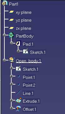
Every Shape/Wireframe features are created in Open Body features, those federator features are used to group specifications in dedicated bags in order to clarify the Design of a Complex V5 Part. An Open Body can be created inside an Open Body, there can be as many Open Body as the user wants. An Open Body can't be created in a Part Body.
Open Body group features, and the order in this Open Body is not significant (in Part Body the order is significant and the reorder capability enable the user to modify the order inside a Part Body, and thus modify the design intent).
An open body feature is like a bag whose responsibiliity is to aggregate other features, like other open bodies or shape design features (Wireframe, Skins and Transformations.) An open body has a structuring role that can be used to split the design of a complex part in several goup of connex design features. This enables any user to better understand the way a part has been designed.
|
In CATIA V5 applications, the first open body feature is created under the part feature itself, either when the first shape design feature is created or when referencing external specifications (Multi-model link, V4 import capability, etc.) |
[Top]
This article has demonstrated the difference between a Form feature and a Shape feature.
[Top]
| [1] | Creating an Open Body |
| [2] | Inserting a Shape Feature in an Open Body |
| [3] | Feature Modeler Overview |
| [4] | Performing the Replace on a Mechanical Feature |
| [5] | Basic Topological Operators |
| [Top] | |
| Version: 1 [Apr 2000] | Document created |
| [Top] | |
Copyright © 2000, Dassault Systèmes. All rights reserved.