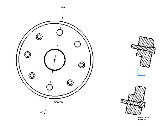
Fig. 1 represents the Drawing document used by the use case.
Mechanical Design |
Drafting |
Editing Generated Shapes in Generative ViewsHow to access generated shapes in generative views |
| Use Case | ||
AbstractThis article discusses the CAADrwGenShape use case. This use case explains how to retrieve generated shapes in a generative view. A generated shape is the feature aggregating a pattern. For example, when a section view is created, a pattern is created to show the cut. Such a pattern is aggregated by a generated shape. Note: Generated Shape is called GenShape is a synonym for Generated Shape. |
This use case is intended to show you how to access generated shapes in generative views.
[Top]
CAADrwGenShape is a use case of the CAADraftingInterfaces.edu framework that illustrates DraftingInterfaces framework capabilities.
[Top]
|
|
|
Fig. 1 represents the Drawing document used by the use case. |
This Use Case shows how to retrieve contours of GenShape. In the section view of Fig 1, there are 6 contours.
[Top]
To launch CAADrwGenShape, you will need to set up the build time environment, then compile CAADrwGenShape along with its prerequisites, set up the run time environment, and then execute the use case [1].
When you launch the use case, pass the full pathname of the Drawing file as argument. A Drawing file is delivery in the following path: CAADraftingInterfaces.edu\FunctionTests\InputData\DrawingForGenShapeUseCase.CATDrawing.
e:> mkrun -c cmd CAADrwGenShape c:\...\DrawingForGenShapeUseCase.CATDrawing |
$ mkrun -c cmd CAADrwGenShape /u/users/.../DrawingForGenShapeUseCase.CATDrawing |
[Top]
The CAADrwGenShape use case is made of a single source file named CAADrwGenShape.cpp located in the CAADrwGenShape.m module of the CAADraftingInterfaces.edu framework:
| Windows | InstallRootDirectory\CAADraftingInterfaces.edu\CAADrwGenShape.m\ |
| Unix | InstallRootDirectory/CAADraftingInterfaces.edu/CAADrwGenShape.m/ |
where InstallRootDirectory is the directory where the CAA
CD-ROM is installed.
[Top]
There are seven steps in CAADrwGenShape:
[Top]
int main(int    iArgc,   // Number of arguments (1)
         char** iArgv)   // Path to the new *.CATDrawing document
{
 // Check arguments
if(2 != iArgc) return 1;
const char *pfileNameDrawing = iArgv[1];

// return code error
int rc =0;

// CREATE THE SESSION
// ==================

CATSession *pSampleSession = NULL;
HRESULT hr = ::Create_Session("SampleSession",pSampleSession);
if (FAILED(hr)) return 1;
CATDocument* pDocDrawing = NULL; if (FAILED(CATDocumentServices::OpenDocument(pfileNameDrawing, pDocDrawing)))
{
// Ends session
::Delete_Session("SampleSession");
return 2;
}
...
|
This section represents the usual sequence for loading a CATIA document [2].
[Top]
...
CATIDftDrawing *piDrawing = NULL;
CATIDftDocumentServices *piDftDocServices = NULL;

if (SUCCEEDED(pDocDrawing->QueryInterface(IID_CATIDftDocumentServices, (void **)&piDftDocServices)))
{
  if (SUCCEEDED(piDftDocServices->GetDrawing(IID_CATIDftDrawing, (void **)&piDrawing)))
  {
    piDftDocServices->Release();
    piDftDocServices=NULL;
  }
  else
  {
    piDftDocServices->Release();
    piDftDocServices=NULL;

    // Ends session
    ::Delete_Session("SampleSession");
    return 3;
  }
}
else
{
  // Ends session
  ::Delete_Session("SampleSession");
  return 3;
}
...
|
The root feature of a drawing document is the Drawing, that is, the feature
that implements the CATIDftDrawing interface. We can get a pointer to
CATIDftDrawing using the CATIDftDocumentServices interface, which is
implemented by the document. The GetDrawing method first argument
is the CATIDftDrawing interface IID.
[Top]
...
  // Active view retrieval from the drawing root
  // ===========================================
  if (piDrawing)
  {
    CATIDftView *piCurrentView = NULL;
    if (SUCCEEDED(piDrawing->GetActiveView(&piCurrentView)))
    {
      // RETRIEVE GENERATED SHAPES IN THE VIEW
      // ==========================================
      if (NULL != piCurrentView)
      {
        CATIUnknownList * piList = NULL;
        if (SUCCEEDED( piCurrentView->GetComponents(IID_CATIDrwGenDrawShape,&piList)))
        {
          if (piList)
          {
            unsigned int piListSize = 0;
            piList->Count(&piListSize);

            CATIDrwGenDrawShape * piGenShape = NULL;
            IUnknown * item = NULL;
            CATUnicodeString PartName;

            // Loop on all Generated shapes of the view.
            for(unsigned int i=0 ; i<piListSize ; i++)
            {
              if( SUCCEEDED( piList->Item(i, &item) ) )
              {
                if(SUCCEEDED( item->QueryInterface(IID_CATIDrwGenDrawShape, (void**) & piGenShape) ) )
                {
... |
A Drawing may contain several sheets, but only one is current at a time. The current sheet is the sheet containing the active view, that is the view currently edited. GetActiveView method defined in CATIDftDrawing interface returns the active view of active sheet in the drawing document. GetComponents method is a generic method to retrieve all elements identified by an IID. These elements are returned in a CATIUnknownList.
[Top]
...
CATListOfInt ListOfNbPtPerContour;
CATListPtrCATMathPoint2D ListOfPoints;
int NbContour=0;
if (piGenShape && SUCCEEDED(piGenShape->GetDescription(NbContour, ListOfNbPtPerContour, ListOfPoints)))
{
  // Check geometry
  for (int numcont=1 ; numcont<=NbContour ; numcont++)
  {
    int NbPtcnt = ListOfNbPtPerContour[numcont];
    for (int numpt=1 ; numpt<=NbPtcnt ; numpt++)
    {
      // Get coordinates of the shape
      CATMathPoint2D *tmpt = ListOfPoints[numpt];
      if (tmpt)
      {
        cerr << " Number point = " << numpt << " X= = "<< tmpt->GetX() << "Y = " << tmpt->GetY() << endl;
        // Memory clean
        delete tmpt , tmpt=NULL;
      }
    }
  }
}
...
|
This sample show how to retrieve points defining the contours by using
GetDescription method.
[Top]
...
IUnknown *piUnk=NULL;
if (SUCCEEDED(piGenShape->GetProduct(IID_CATIProduct,&piUnk)))
{
  CATIProduct *piProd =NULL;
  if (SUCCEEDED(piUnk->QueryInterface(IID_CATIProduct,(void **)&piProd)))
  {
    CATUnicodeString instanceName;

    // Get part instance name on which generated shape is associated.
    if (SUCCEEDED (piProd->GetPrdInstanceName( instanceName ) ))
    {
      cerr << "Part instance name"<< instanceName.CastToCharPtr() <<endl;
    }
    piProd->Release();piProd=NULL;
  }
  piUnk->Release();piUnk=NULL;
}
...
|
[Top]
...
// Get Pattern used by the generated shape,
CATIDftPattern *piDftPattern=NULL;
if (SUCCEEDED(piGenShape->GetPattern(&piDftPattern)))
{
  int patternType=0;
  piDftPattern->GetPatternType(&patternType);
  if (patternType == 1)
  cerr << "Hatching Pattern found" << endl;
  piDftPattern->Release(),piDftPattern=NULL;
}
...
|
This section represents the usual sequence to retrieve the Pattern [3].
[Top]
...
  // Save the result
  rc = CATDocumentServices::SaveAs(*pDoc, (char *)fileName);
  ... // Check rc
  rc = CATDocumentServices::Remove (*pDoc);
  ... // Check rc
  // Ends session and drops document
  rc = ::Delete_Session("SampleSession");
  ... // Check rc

  return 0;
}
|
This section represents the usual sequence for saving a newly created CATIA document [2].
[Top]
This use case shows the way to :
[Top]
| [1] | Building and Lauching CAA V5 Samples |
| [2] | Load an existing Document |
| [3] | Creating a Pattern |
| [Top] | |
| Version: 1 [May 2004] | Document created |
| [Top] | |
Copyright © 2004, Dassault Systèmes. All rights reserved.