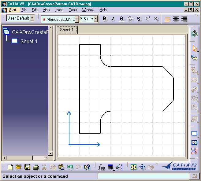
Fig. 2: The Start Up Model processed by CAADrwCreatePattern batch.
Mechanical Design |
Drafting |
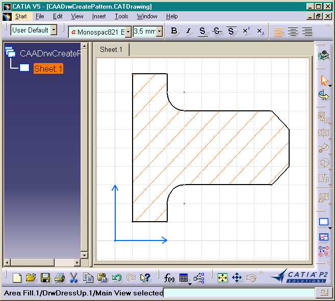
Creating a Hatching Pattern On 2D GeometryHow to use area fill interfaces |
| Use Case | ||
AbstractThis article discusses the CAADrwCreatePattern.cpp use case. This use case explains how to create a hatching pattern on 2D geometry. |
In this use case you will learn how to create a hatching pattern on 2D geometry.
[Top]
CAADrwCreatePattern is a use case of the CAADraftingInterfaces.edu framework that illustrates DraftingInterfaces framework capabilities.
[Top]
This sample creates a hatching pattern on 2Dgeometry in batch mode:
|
|
|
Fig. 2: The Start Up Model processed by CAADrwCreatePattern batch. |
|
|
[Top]
To launch CAADrwCreatePattern, you will need to set up the build time environment, then compile CAADrwCreatePattern along with its prerequisites, set up the run time environment, and then execute the use case [1].
When you launch the use case, pass the full pathname of the file into which you you want to store the created document as argument: for example Result.CATDrawing. The input file CAADrwCreatePattern.CATDrawing containing the 2D geometry is stored on CAADraftingInterfaces.edu/CNext/resources/graphic directory.
e:> CAADrwCreatePattern CAADrwCreatePattern.CATDrawing Result.CATDrawing |
$ CAADrwCreatePattern /u/users/CAADrwCreatePattern.CATDrawing Result.CATDrawing |
[Top]
The CAADrwCreatePattern use case is made of one source file named CAADrwCreatePattern.cpp located in the CAADrwCreatePattern.m module of the CAADraftingInterfaces.edu framework:
| Windows | InstallRootDirectory\CAADraftingInterfaces.edu\CAADrwCreatePattern.m\ |
| Unix | InstallRootDirectory/CAADraftingInterfaces.edu/CAADrwCreatePattern.m/ |
where InstallRootDirectory is the directory where the CAA CD-ROM
is installed.
[Top]
There are five steps in CAADRWCreatePattern:
[Top]
int main(int    iArgc,   // Number of arguments (1)
         char** iArgv)   // Path to the new *.CATDrawing document
{
   // Check arguments
   if(3 != iArgc) return 1;
   const char *pfileName = iArgv[1];
   const char *pfileNameOut = iArgv[2];


   // CREATE THE SESSION
   // ==================

   CATSession *pSampleSession = NULL;
   HRESULT hr = ::Create_Session("SampleSession",pSampleSession);
   if (FAILED(hr)) return 1;


   // READ THE DRAWING DOCUMENT
   // =========================

   CATIDrawing *piDrawing = NULL;
   CATIDftDocumentServices *piDftDocServices = NULL;
   CATDocument* pDoc = NULL;
   CATIContainer_var spDrwcont;
   CATISpecObject_var spSpecObj;
   CATIDrwFactory_var spDrwFact;
   if (FAILED(CATDocumentServices::OpenDocument(pfileName, pDoc)))
   {
      // Ends session
      ::Delete_Session("SampleSession");
      return 2;
   }

   ...
|
This section represents the usual sequence for creating a CATIA document.
[Top]
...
  if (SUCCEEDED(pDoc->QueryInterface(IID_CATIDftDocumentServices, (void **)&piDftDocServices)))
   {
      piDftDocServices->GetDrawing(IID_CATIDrawing, (void **)&piDrawing);
      piDftDocServices->Release();
      spSpecObj=piDrawing;
      spDrwcont = spSpecObj->GetFeatContainer();
      spDrwFact = spDrwcont;
   }
   else
   {
      // Ends session
      ::Delete_Session("SampleSession");
      return 3;
   }
...
|
The root feature of a drawing document is the Drawing that is the feature that implements the CATIDrawing interface. We can get a pointer to CATIDrawing using the CATIDftDocumentServices interface, which is implemented by the document. The GetDrawing method first argument is the interface you want to get on the drawing.
[Top]
...
  // MAIN VIEW RETRIEVAL
   // ===================

   // We are working in main view of the current sheet
   CATISheet_var spSheet = piDrawing->GetCurrentSheet();
   piDrawing->Release();
   CATIView_var spMainView = spSheet->GetMainView();


   // GEOMETRY READING IN THE MAIN VIEW
   // =================================
   // The drawing startup model contains a profile made of lines and circles. So these
   // elements are arranged.

   spSheet->SetCurrentView(spMainView);
   CATISketch_var spSketch = spMainView;
   CATLISTV(CATISpecObject_var) ListValidElem;
   CATListValCATI2DWFGeometry_var spListElem;
   CATUnicodeString namealias;
   hr = spSketch->GetComponents(CATI2DCurve::ClassName(),spListElem);
   for (int i=1; i<=spListElem.Size(); i++)
   {
      // Get all geometric elements containing the string "area" in their external name.
      namealias = CATIAlias_var(spListElem[i])->GetAlias();
      if (namealias.SearchSubString("area") != -1)
      {
         ListValidElem.Append(spListElem[i]);
      }
   }
...
|
The 2D geometry in the Start Up CATDrawing Document is identified by external name applied on each element. These elements are automatically arranged by the way to used to create it: Profile command in Geometry Creation Toolbar. If these elements are not arranged, the area fill will be created with a wrong display.
[Top]
...
 CATIDftHatchingPattern *iHatching = NULL;

	if (SUCCEEDED( spDrwFact->CreateHatchingPattern(IID_CATIDftHatchingPattern, (void **) &iHatching) ))
   {
      hr = iHatching->SetOffset(15.0);
      hr = iHatching->SetAngle ((double)  ( CATRadianToDegree * CATPIBY4));
      hr = iHatching->SetPitch (8.0);
      hr = iHatching->SetTexture (1);
      hr = iHatching->SetThikness(1);
      hr = iHatching->SetColor(4);

   }
   else
   {
      // Ends session
      ::Delete_Session("SampleSession");
      return 4;
   }
...
|
To create geometric elements in a view, the view has to be current.
[Top]
...
   // BreakElem are relimited elements to create the area fill domain.

   // Gets the BreakElem factory
   CATIDrwBreakElemFactory_var spBreakElemfact;
   if (spDrwcont != NULL_var)
      spBreakElemfact = spDrwcont;
   else
   {
      if (iHatching) iHatching->Release();
      // Ends session
      ::Delete_Session("SampleSession");
      return 5;
   }
   CATLISTV(CATISpecObject_var) ListBreakElem;
   CATI2DCurve_var spCurveElm;
   double pStartParam, pEndParam, pInter ;
   int index=0, creation=0, containment=0;

   // Loop on geometry elements
   for (i=1; i<=spListElem.Size(); i++)
   {
      spCurveElm = spListElem[i];
      spCurveElm->GetParamExtents(&pStartParam,&pEndParam);

      if (pStartParam > pEndParam)
      {
         pInter = pStartParam;
         pStartParam = pEndParam;
         pEndParam = pInter;
      }

      CATIDrwBreakElem_var spBreakElem = spBreakElemfact-> CreateBreakElem(spCurveElm,pStartParam,pEndParam,"",index,creation,containment);
      ListBreakElem.Append(spBreakElem);
   }
...
|
[Top]
...
   // AREA FILL CREATION
   // =================

   // Notes: The area fill object will be correctly created if BreakElem elements are
   // arranged in the ListeBreakElem list.

   // Gets the annotation factory
   CATIDrwAnnotationFactory_var spAnnFactory = spMainView;

   CATIDrwAreaFill_var AreaFill;

   CATISpecObject *piSpecObj = NULL;
   if (SUCCEEDED(iHatching->QueryInterface(IID_CATISpecObject, (void **)&piSpecObj)))
   {
      AreaFill = spAnnFactory -> CreateDrwAreaFill(ListBreakElem, piSpecObj, "");
      piSpecObj->Release();
   }
   else
   {
      if (iHatching) iHatching->Release();
      // Ends session
      ::Delete_Session("SampleSession");
      return 5;
   }

   // memory cleaning
   if (iHatching) iHatching->Release();

...
|
[Top]
...
  // Save the result
  CATDocumentServices::SaveAs(*pDoc, (char *)pfileNameOut);
   CATDocumentServices::Remove (*pDoc);
   //Ends session and drops document
   ::Delete_Session("SampleSession");

   return 0;
}
|
This section represents the usual sequence for saving a newly created CATIA document.
[Top]
This use case shows the objects and interfaces used when creating an area fill in a main view of a CATDrawing document. The Area fill is created using the CATIDftAnnotationFactory interface.
[Top]
| [1] | Building and Lauching CAA V5 Samples |
| [2] | Open a Document |
| [Top] | |
| Version: 1 [Jan 2001] | Document created |
| [Top] | |
Copyright © 2001, Dassault Systèmes. All rights reserved.