Mechanical Design |
Drafting |
Creating Dimension System in a CATDrawing DocumentHow to create dimension system on interactive |
| Use Case | ||
AbstractThis article discusses the CAADrwCreateDimSyst use case. This use case explains how to create dimension system on interactive in a CATDrawing document. |
In this use case you will learn how to create dimension system on interactive geometry. The dimension system is a set of dimensions. The positioning of these dimensions depend of the type of the dimension system: Cumulated, Stacked or Chained. This sample is an interactive command which create a Stacked dimension system, from extremity points of line put in the CSO.
[Top]
CAADrwCreateDimSyst is a use case of the CAADraftingInterfaces.edu framework that illustrates DraftingInterfaces framework capabilities.
[Top]
This use case is made of a state command that creates a dimension system from points already put in the CSO.
|
|
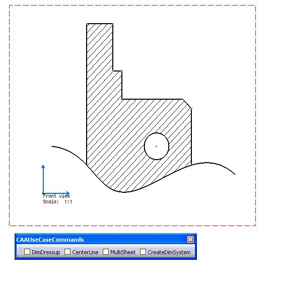
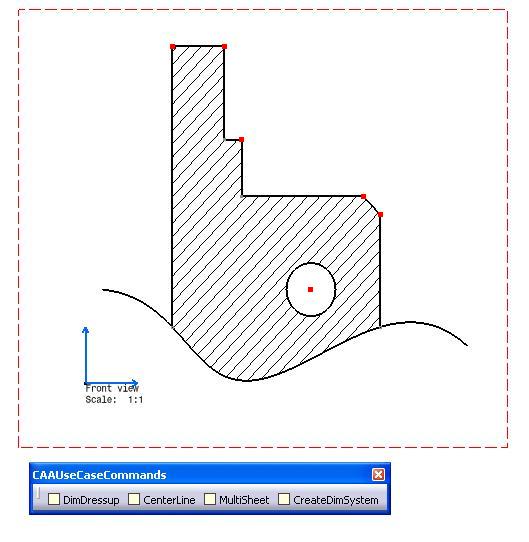
This picture represents geometry created by Interactive Drafting product
 |
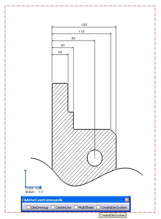 |
This picture shows the dimension system created by the CAA command CreateDimSystem.
[Top]
To launch CAADrwCreateDimSyst, you will need to set up the build time environment, then compile CAADrwCreateDimSyst and CAADrwAddin along with its prerequisites, set up the run time environment.[1].
Top]
The CAADrwCreateDimSyst use case is made of two source files named CAADrwCreateDimSystCmd.h and CAADrwCreateDimSystCmd.cpp located in the CAADrwCreateDimSyst.m module of the CAADraftingInterfaces.edu framework:
| Windows | InstallRootDirectory\CAADraftingInterfaces.edu\CAADrwCreateDimSyst.m\ |
| Unix | InstallRootDirectory/CAADraftingInterfaces.edu/CAADrwCreateDimSyst.m/ |
where InstallRootDirectory is the directory where the CAA CD-ROM
is installed.
[Top]
There are two steps in CAADrwCreateDimSyst:
[Top]
void CAADrwCreateDimSystCmd::BuildGraph()
{
  // Creation of the acquisition agent
  _pObjectAgent = new CATPathElementAgent("_pObjectAgent A");
  _pObjectAgent ->SetBehavior( CATDlgEngWithPrevaluation |
  CATDlgEngMultiAcquisition |
  CATDlgEngWithCSO);

  // We only want to get points
  _pObjectAgent ->AddElementType("IDMPoint2D");
  AddCSOClient(_pObjectAgent);

  // States definition
  CATDialogState* pState1 = GetInitialState("Sel points");
  pState1->AddDialogAgent(_pObjectAgent);

  // Transition definition
  AddTransition(pState1, NULL, IsOutputSetCondition(_pObjectAgent),
  Action((ActionMethod)&CAADrwCreateDimSystCmd::CreateDimSyst, NULL, NULL));
}
|
In this section we create a CATPathElementAgent and set the corresponding element type to IDMPoint.
[Top]
boolean CAADrwCreateDimSystCmd::CreateDimSyst(void *iData)
{
  CATSO* pObjSO = _pObjectAgent->GetListOfValues();
  CATPathElement *pElemPath = NULL;

  // Dimension System creation:
  // ==========================
  if (NULL != pObjSO)
  {
    // We will scan the CSO from the begining
    pObjSO->InitElementList();
    CATIDrwAnnotationFactory *piDrwFact = NULL;
    IDMPoint2D *piFirstElem = NULL;
    IDMPoint2D *piSecondElem = NULL;
    IDMPoint2D *piNextElem = NULL;
    CATIDrwDimSystem *piDimSyst = NULL;
    CATIDrwDimDimension *piDim = NULL;
    CATDimSystemDefinition sysDef;
    sysDef.SystemType = StackedDimSystem;
    sysDef.SetOffsetMode(ConstantOffsetSystem);
    sysDef.SetValueAlignmentMode(OnRefLineSide);
    sysDef.SetValueOffset(100.0);
    while (NULL != (pElemPath = (CATPathElement*)pObjSO->NextElement()) )
    {
      if (NULL == piFirstElem)
      {
        piFirstElem = (IDMPoint2D *)pElemPath->FindElement(IID_IDMPoint2D);
        piDrwFact = (CATIDrwAnnotationFactory *)pElemPath->FindElement(IID_CATIDrwAnnotationFactory);
      }
      else if (NULL == piSecondElem)
      {
        piSecondElem = (IDMPoint2D *)pElemPath->FindElement(IID_IDMPoint2D);
        // Dimension creation
        if (piSecondElem && piFirstElem)
        {
          CATDrwDimType dimType = DrwDimDistance;
          CATDimDefinition dimDef;
          dimDef.OrientationReference = ParallelDim;
          dimDef.Orientation = DrwDimAuto;
          CATIUnknownList * piSelectionsList =NULL;
          CATIUnknownListImpl * piListsel = new CATIUnknownListImpl();
          piListsel->QueryInterface(IID_CATIUnknownList, (void **) &piSelectionsList);
          piListsel->Release(); piListsel=NULL;

          IUnknown * piLine1 = NULL;
          IUnknown * piLine2 = NULL;
          piFirstElem->QueryInterface(IID_IUnknown, (void **)&piLine1);
          piSecondElem->QueryInterface(IID_IUnknown, (void **)&piLine2);
          if (piSelectionsList)
          {
            piSelectionsList->Add(0, piLine1);
            piSelectionsList->Add(1, piLine2);
          }
          double pt1[2],pt2[2];
          piFirstElem->GetPointData(pt1);
          piSecondElem->GetPointData(pt2);
          double * pts[2] = { NULL, NULL };
          pts[0] = pt1;
          pts[1] = pt2;
          dimDef.Orientation = DrwDimAuto;
          if (piDrwFact)
          {
            piDrwFact->CreateDimension(piSelectionsList,pts,dimType,&dimDef,&piDim);
            piDrwFact->CreateDimSystem(piDim,&sysDef,&piDimSyst);
          }
          if (piLine1) piLine1->Release(),piLine1 = NULL;
          if (piLine2) piLine2->Release(),piLine2 = NULL;
          if (piSelectionsList) piSelectionsList->Release(),piSelectionsList=NULL;
        }
      }
      else if (NULL == piNextElem)
      {
        piNextElem = (IDMPoint2D *)pElemPath->FindElement(IID_IDMPoint2D);
        // Dimension system creation
        if (piNextElem && piDimSyst && piDim)
        {
          double pt1[2];
          piNextElem->GetPointData(pt1);
          CATMathPoint2D ptSel(pt1[0],pt1[1]);
          CATIDrwDimDimension *myDimToAdd = NULL;
          piDimSyst->AddDimension((CATBaseUnknown *)piNextElem,myDimToAdd,&ptSel);
        }
        if (piNextElem) piNextElem->Release(),piNextElem=NULL;
      }
      else
        cout << "invalid input" << endl;
    }
|
The acquisition agent did put the selected points into the CSO. So we get
the SO and loop on it. A dimension is created from the 2 first points in the SO,
then the dimension system is created from this dimension by using
CreateDimSystem method defined in CATIDrwAnnotationFactory interface,
Others dimensions are created in the dimension system by using
AddDimension method defined in CATIDrwDimSystem interface.
CATDimSystemDefinition class allows to initialize a set of parameters for the
dimension system definition as the type of the dimension system (Chained,
Cumulated, Stacked).
[Top]
// Dimension System modifications:
// ===============================
if (piDimSyst)
{
  // Get the master dimension for dimension system moving
  CATIDrwDimDimension *piMasterDim=NULL;
  CATMathPoint2D ptPos(150.0,230);
  piDimSyst->GetMasterDimension(&piMasterDim);
  if (piMasterDim)
  {
    piMasterDim->MoveDimensionLine (ptPos);
    CATISpecObject_var spDimSpec = piMasterDim;
    if (!!spDimSpec)
      spDimSpec->Update();
    piMasterDim->Release();piMasterDim=NULL;
  }
  // Dimension system properties modification
  CATIDrwStackedDimSystem *piDrwStkSyst=NULL;
  if (SUCCEEDED(piDimSyst->QueryInterface(IID_CATIDrwStackedDimSystem,(void **)&piDrwStkSyst)))
  {
    double valueoffset = 12.0;
    piDrwStkSyst->SetValueAlignmentMode(AlignedOnCenter);
    piDrwStkSyst->SetOffset(valueoffset);
    piDrwStkSyst->Release();piDrwStkSyst=NULL;
  }
  piDimSyst->LineUp(2);
}
|
The modification of dimension system dimensions line is insured by the moving of the dimension line of the "master" dimension. At the end of this operation, LineUp method allows to update the positioning of all others dimension line of the dimensions system.
[Top]
This use case shows how to create a state command creating and modifying a dimension system.
[Top]
| [1] | Building and Lauching a CAA V5 Use Case |
| [2] | Implementing the Statechart Diagram |
| [Top] | |
| Version: 1 [March 2008] | Document created |
| [Top] | |
Copyright © 2000, Dassault Systèmes. All rights reserved.