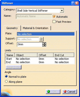
Select from the Category drop down list. You can select More to display the Class Browser, and select from what is available in the catalog.
- A plane.
- A surface that intersects the plate. You can create your own surface if you need to.
- A grid.
The stiffener is placed when you select a support. The support defines a trace on the plate that the stiffener follows when it is placed.
- Click the button next to the Support field to display the Elements List. From the list, select the support. You can use the Remove and Replace buttons.
- Right click in the Support field, and select Select Reference Plane. This displays the Plane Systems dialog box. See Using the Reference Plane Browser in the Structure Functional Design User's Guide for an explanation of the Plane Systems dialog box.
Warning: It is important to select a Support that is compatible with the selected Category. For more information about Selecting a Support, see Defining Molded Conventions.
When the Fast Preview checkbox is cleared or when you click OK, both the trace and the full presentation of the stiffener is generated.
| Fast Preview selected | Fast Preview deselected |
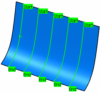 |
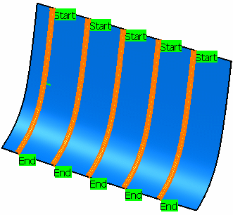 |
This is the value by which the stiffener will be offset from the support you selected. The value is expressed in the units selected in your workbench.
Enter a negative (-) sign in front of the value to offset it in the opposite direction.
You can swap the default limits by clicking the Swap Ends button. (Click again to toggle).

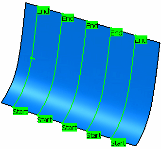
You can define the stiffener limits. However, the Swap Ends button becomes unavailable once a limit is defined.
In the Name field, select Start and select a starting limit. You can select a plane, plate, another stiffener or a surface. The stiffener is limited as soon as you make your selection.
Use the same method to define the End.
This image shows a stiffener that has not been limited.

This image shows a stiffener that has been limited at the end.

Under Offset, you can define the offset value of each stiffener limit.
|
|
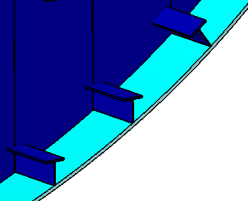 |
NOTE: When creating a stiffener using a curve as a support, the Along plane angle has no effect. Use the Normal to plate option.
