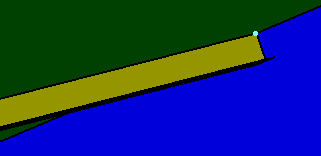
The procedure, described below, applies to both the Structure Detail Design and Structure Functional Design applications. Where indicated, specific steps apply to just one of the applications.
- Using the Stiffener Dialog Box: This method can be used for placing end cuts on stiffeners only.
- Using the End Cut Command: This method can be used for placing end cuts on profiles, such as stiffeners and beams.
Using the Stiffener Dialog Box
To place contextual end cuts, you need to define limits on the stiffener. If you select a contextual end cut (Cutback or UDF contextual) to be placed on a stiffener without limits, a warning is displayed.

In this example, the stiffener is limited by the longitudinal bulkhead.
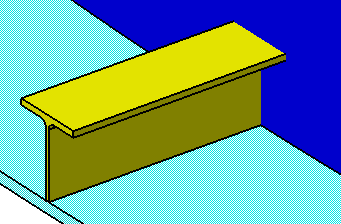
The Stiffener dialog box displays with information for the selected stiffener. See Using the Stiffener Dialog Box.
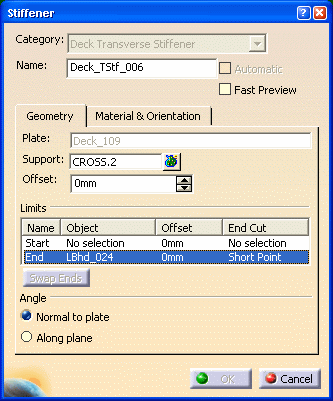
2.
Right-click the stiffener with the Start or End limit (the Start limit in this example), and select Define End Cut.
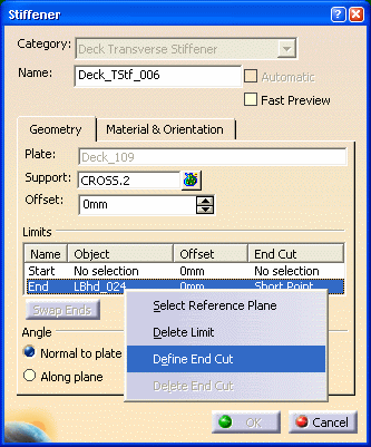
The End Cut dialog box displays.
From the list, you can select the following Cutback end cuts. In the dialog box, an image of the selected end cut displays.
Trim type
Short Point
 Long Point

Weld type
Weld
 Metal to Metal
These end cuts require less CPU and memory than UDF end cuts (custom).
Certain UDF end cuts (custom) are also provided, and you can customize these, as required.
The example below uses a Web Snipe Radius, a UDF end cut.
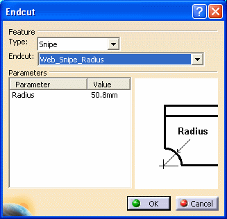
Click OK to return to the Stiffener dialog box. The selected end cut displays under the End Cut column.

Click OK in the Stiffener dialog box. The end cut is placed on the stiffener (see images below).
Using the End Cut command
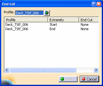
You can also pre-select the profile and then click the End Cut button.
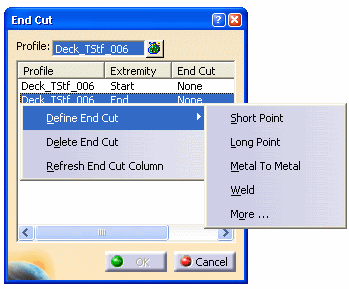
You can also right-click the extremity in your 3D session.
1) Standard end cuts
2) Contextual end cuts. It is mandatory for a profile to have limits to place these end cuts.
- Cutbacks, such as Short Point, Long Point, Metal to
Metal, and Weld are contextual end cuts and require the stiffener to have a limit.
If the stiffener does not have a limit and you select Define End Cut and then a cutback (Short Point, Long Point,
Metal
to Metal, or Weld), an error message is displayed in the End Cut column. Right-click and select
Refresh End Cut Column to start again.
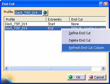
If the stiffener does not have a limit, select More. The End Cut dialog box displays. Select the Type and the End Cut. In your 3D session, select the limit. The selected limit displays as Object in the Inputs tab.
| Short Point end cut |
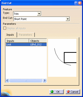 |
- UDF end cuts (Custom end cuts). Standard or Contextual.
a) Standard, such as Web Snipe Radius end cut. Select More. The End Cut dialog box displays. Select the Type and End Cut. The parameter values are displayed. You can modify these values, as required.
b) Contextual, such as T-CTX-Shape end cut. Select More. The End Cut dialog box displays. Select the Type and End Cut. Such end cuts require more inputs from the user. Click the Inputs tab and select the required Shape in the 3D session. The selected shape is displayed as Object. You can also modify the parameter values, as required.
| UDF end cut (Standard) | UDF end cut (Contextual) |
 |
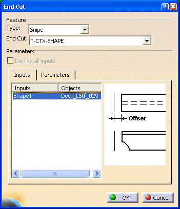 |
- Built-in end cuts are standard end cuts, such as Web Snipe Radius R1. Select More. The End Cut dialog box displays. Select the Type and End Cut. The parameter values are displayed. You can modify these values, as required.
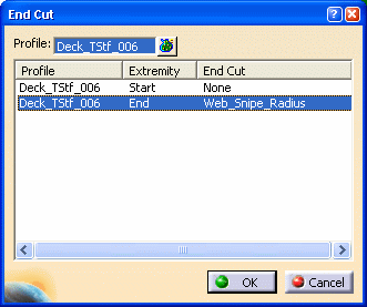
The image below shows a Web Snipe Radius end cut placed on a stiffener.
For Structure Detail Design:
In the 3D session, you can see the end cut placed on the stiffener.
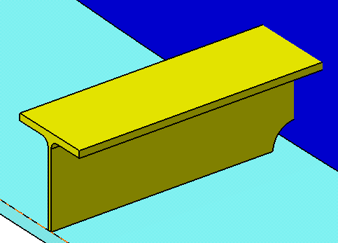
For Structure Functional Design:
In the 3D session, you see a blue dot, which represents the end cut.
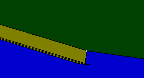
You also see ConnectionsSet in the specifications tree. ConnectionsSet is where information on all connections (such as end cuts) is stored and managed.
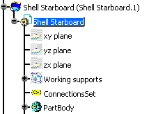
ConnectionsSet appears only once on the specifications tree, regardless of the number of end cuts or slots in your 3D session.
If an object such as a bulkhead is moved, the end cut, represented by the blue dot, does not move with the bulkhead, and remains where placed originally in the 3D session.
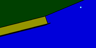
So you must update ConnectionsSet.
Right click on ConnectionsSet in the specifications tree. Select ConnectionsSet Object - Update from the drop down menus.
A message box indicates the information is updated.
After clicking OK, the end cut (as a blue dot) moves beside stiffener, wherever appropriate.
