Some Definitions
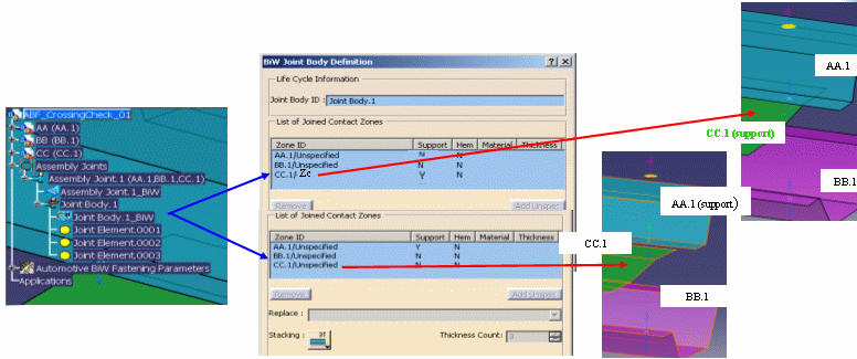
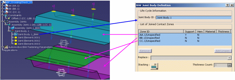
- A Joint Body is a list of joined positioned part zones. It has one and only one zone specified as "support", for a "Lap" stacking type.
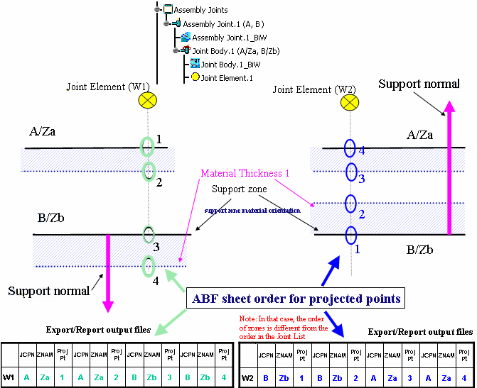
- In flat reports, the list of zones is sorted out according to the ABF support zone material orientation that corresponds to the GSD material orientation of the support zone.
- The ABF sheet order for projected points is defined according to the support zone material orientation. The order of the projected points increases depending on the direction of the support zone material orientation (see following picture).
In the picture below, all thicknesses are crossed by a spot projection, and the ordering criteria is applied.
The following examples list the cases where the ordering criteria cannot be applied.
The spot point cannot be projected on at least one of the joined parts
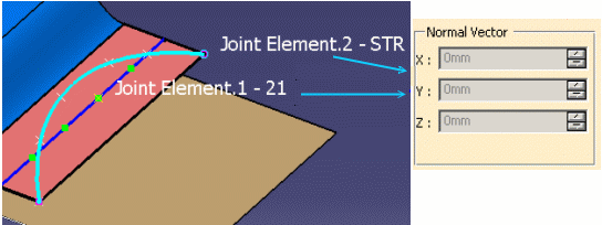
1. The BiW Fastener does not have a normal vector
3D Visualization: only the Shape Representation and the ID is displayed.
- No specified normal vector detected by the Normal Vector Alignment Analysis command.
- The fastener's normal vector coordinates is marked by 'N/A' in all the Export/Report/Flat Report output files.
- The fastener's crossed thicknesses attributes are ordered along the associated joint body zones list. Computed projections on zones that are not crossed are marked by 'N/L' in all Export/Report output files.
2. The BiW Fastener does not have a projection on the support contact zone or its projection does not cross a zone
- The thicknesses stack-up order is not displayed.
- No crossed zones are detected by the Thickness Crossing Analysis command.
- The list of fastener's crossed thicknesses attributes are ordered along the associated joint body zones list. Computed projections that are not crossed are marked by 'N/L' in all the Export/Report/Flat Report output files.
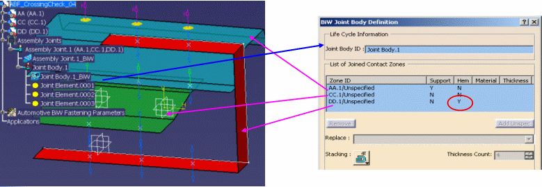
3. The fastener does not cross one part of hem zone
- The thicknesses stack-up order is not displayed.
- No crossed zones detected by the Thickness Crossing check analysis.
- The fastener's crossed thicknesses attributes are ordered along associated joint body zones list in the Export/Report/Flat Report output files.
- The fastener's hem zone crossed thicknesses attributes are ordered along the nearest zone of the fastener location, following the projection axis.
4. The distance between projection points is lower than 10- (identical points standard tolerance)
- The thicknesses stack-up order is not displayed.
- The fastener crossed thicknesses attributes are ordered along the associated joint body zones list in all the Export/Report/Flat Report output files.
![]()
