This task will show you how to define the restraint excitation set in a:
Defining a restraint excitation set allows you to define an imposed motion of the support in the frequency domain or in the time domain.
![]()
Only available with the Generative Dynamic Response Analysis (GDY) product.
Harmonic Dynamic Response Case
Open the sample57_1.CATAnalysis document from the samples directory.
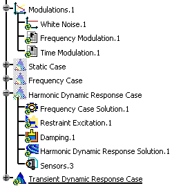
- Insert a Harmonic Dynamic Response Analysis Case (and choose a restraint excitation set).
- Define a white noise modulation or define a frequency modulation.
-
Double-click the restraint excitation object belonging to the harmonic dynamic response case.
In this particular case, double-click Restraint Excitation.1. under the Harmonic Dynamic Response Case set.
The Restraint Excitation Set dialog box appears.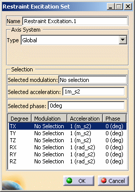
- Name: gives the name of the restraint excitation set. If needed, you can modify it.
- Axis System:
- Type:
- Global: if you select the Global Axis system, the components field will be interpreted as relative to the fixed global rectangular coordinate system.
- User: if you select a user-defined axis system,
the components will be interpreted as relative to the specified
rectangular coordinate system.

- Current axis: lets you select the desired axis system.
- Local orientation: (Cartesian) the components are interpreted as relative to a fixed rectangular coordinate system aligned with the Cartesian coordinate directions of the User-defined Axis.
- Type:
- Selection:
- Selected modulation: lets you select a white noise
modulation or a frequency modulation.

You cannot select a time modulation in a harmonic dynamic response analysis case.
- Selected acceleration: lets you select the acceleration that will be modulated.
- Selected phase: lets you specify the phase value.
- Selected modulation: lets you select a white noise
modulation or a frequency modulation.
- Degrees of freedom: gives you the list of the degrees of freedom, the associated modulation, acceleration and phase (T for translation and R for Rotation)
-
Set the desired parameters in the Restraint Excitation Set dialog box.
In this particular example:
- Select the Global option as Axis System Type.
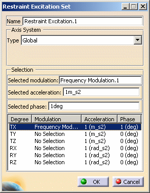
- Select Frequency Modulation.1 as Selected modulation.
- Enter 1m_s2 as Selected acceleration.
- Enter 1deg as Selected phase.
-
Press Enter to update the Restraint Excitation Set dialog box.
The TX degree of freedom is defined and the Restraint Excitation Set dialog box appears as shown below:
You can define other degrees of freedom.
To do this: -
Select an other degree of freedom.
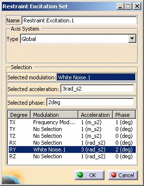
In this particular example, select the RY degree of freedom.
-
Set the different parameters (associated modulation, acceleration and phase).
In this particular example:
- Select the White Noise.1 modulation as Selected modulation.
- Enter 3rad_s2 as Selected acceleration.
- Enter 2deg as Selected phase.
-
Press Enter to update the Restraint Excitation Set dialog box.
The RY degree of freedom is defined and the Restraint Excitation Set dialog box appears as shown below:
-
Click OK.
Transient Dynamic Response Case
Open the sample57_1.CATAnalysis document from the samples directory.
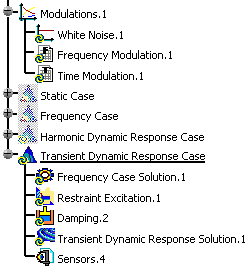
- Insert a Transient Dynamic Response Analysis Case (and choose a restraint excitation set).
- Define a time modulation.
-
Double-click the restraint excitation belonging to a transient dynamic response case.
In this particular case, double-click Restraint Excitation.1.
The Restraint Excitation Set dialog box appears.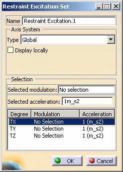
- Name: gives the name of the restraint excitation set. If needed, you can modify it.
- Axis System:
- Type:
- Global: if you select the Global Axis system, the components field will be interpreted as relative to the fixed global rectangular coordinate system.
- User: if you select a User-defined Axis system,
the components will be interpreted as relative to the specified
rectangular coordinate system.
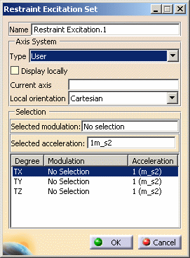
- Current axis: lets you select the desired axis system
- Local orientation: (Cartesian) the components are interpreted as relative to a fixed rectangular coordinate system aligned with the Cartesian coordinate directions of the User-defined Axis.
- Type:
- Selection:
- Selected modulation: lets you select a time
modulation.

You cannot select a frequency modulation.
- Selected acceleration: lets you select the acceleration that will be modulated.
- Selected modulation: lets you select a time
modulation.
- Degrees of freedom: gives you the list of the degrees of freedom, the associated modulation, acceleration (T for translation)
-
Set the desired parameters in the Restraint Excitation Set dialog box.
In this particular example:
- Select the Global option as Axis System Type.
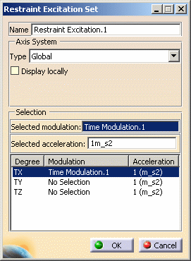
- Select Time Modulation.1 as Selected modulation.
- Enter 1m_s2 as Selected acceleration.
-
Press Enter to update the Restraint Excitation Set dialog box.
The Restraint Excitation Set dialog box appears as shown below:
You can define other degrees of freedom.
To do this: -
Select an other degree of freedom.
In this particular example, select the TY degree of freedom.
-
Set the different parameters (associated modulation and acceleration).
In this particular example:
- Select the White Noise.1 modulation as Selected modulation.
- Enter 3rad_s2 as Selected acceleration.
-
Press Enter to update the Restraint Excitation Set dialog box.
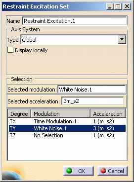
The TY degree of freedom is defined and the Restraint Excitation Set dialog box appears as shown below:
-
Click OK.
![]()