that is to simulate the fibers behavior of a ply in order to detect manufacturability problems.
Within this command you can also:
-
Click the Producibility icon
 in the Flattening toolbar.
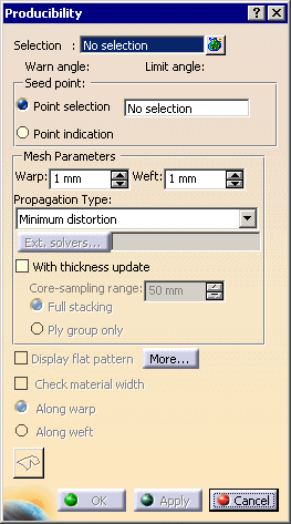
The Producibility dialog box is displayed.
-
Select a ply in the specification tree. Note that multi-selection of plies is possible.
In our scenario, we have selected Ply.1.
The Warn angle and Limit angle values are automatically displayed.

The reference angle is 90 degrees.-
The
Warn angle defines the maximum deformation and
must be +/- 15 degrees according to the reference angle. -
The
Limit angle defines the limit deformation and
must be +/- 30 degrees according to the reference angle.
A color code applies depending on the deformation values:
- blue: the deformation is lower than 15 degrees according to the reference angle,
- yellow: the deformation is between 15 and 30 degrees according to the reference angle,
- red: the deformation is higher than 30 degrees according to the reference angle.
-
The
Warn angle defines the maximum deformation and
-
In the Seed Point field,

select the seed (strategy) point, that is the point used to start the circular propagation of the fibers.
The original fiber directions are displayed on the point (blue for warp and red for weft)
and the dart creation becomes available.

Two methods are available to select the seed point: - Point selection:
you select an existing GSD point.
Should you need to create the seed point,
right-click in the Seed Point field and create the element you need.
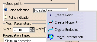
Refer to Generative Shape Design & Optimizer User's Guide for more information.
This point must be selected within the external contour of the ply and lie on the surface. - Point
indication: you pick a point, existing or not
(i.e. you simply pick where you would create a seed point),
within the boundaries of the selected ply.
This allows you a quicker analysis of the producibility as you can restart
the analysis with another point without creating an existing point. - Both mode enables you to store the producibility parameters in the model when you click OK.
- Point selection:
you select an existing GSD point.
-
Define the Warp and Weft values for the fibers meshes.
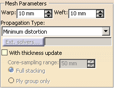
In our scenario we selected 10mm..- Warp: radius used to simulate the fibers behavior along the X direction.
- Weft: radius used to simulate the fibers behavior along the Y direction.
The lower the radius values are, the more precise the meshes will be.
-
Select the propagation type from the list:

- Minimum distortion: deformation computed by the system so as to minimize the distortion.
-
Symmetric: deformation computed symmetrically regarding the
fiber direction.
The system forces the propagation to be symmetrical.
-
Select the With thickness update check box and then the option you need to compute the thickness of plies:
- Core sampling range: enter the required depth of the core sampling.
- Full stacking: to use when the groups of plies are defined on the same reference shell.
-
Ply
group only: to use when groups of plies are defined on various
shells,
as each shell takes into account the plies defined under a group.

You can leave the default value in the Core sampling range field, yet,
make sure the size of the core sampling will not make it go right
through the part if it is in U shape for instance. -
Click Apply to run the analysis and start the simulation.
Fiber meshes display in the 3D geometry.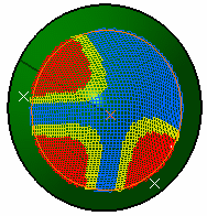
Minimum Distortion In the above picture, the shape of the surface is not symmetrical.
On this non-symmetrical shape, the fiber propagation with the "minimum distortion"
option follows the curvatures of the surface while minimizing the deformation of the fibers.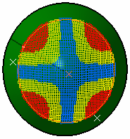
Symmetric With the "symmetric" option, the system forces the fiber propagation to be symmetrical. -
Click More to display the Analysis display mode parameters.

By default, the Deformation option is selected.
The analysis is based on the angle between the fiber meshes. -
Select the Deviation option.
When using this option, the rosette is transferred at each point of the fiber mesh.
The analysis is based on the delta between the theoretical and
the actual fiber angles of each point. -
Enter values for the Warn Angle and the Limit Angle and click Apply to start the analysis.
The simulation is displayed in the 3D geometry.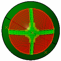
The reference angle is 0 degree.
-
The
Warn angle defines the maximum deformation and
must be +/- 5 degrees according to the reference angle. -
The
Limit angle defines the limit deformation and
must be +/- 10 degrees according to the reference angle.
A color code applies depending on the deviation values:
- green: the deviation is lower than 5 degrees according to the reference angle,
- yellow: the deviation is between 5 and 10 degrees according to the reference angle,
- red: the deviation is higher than 10 degrees according to the reference angle.
-
The
Warn angle defines the maximum deformation and
-
Click Keep.

The curves generated by the producibility analysis are stored in a geometrical set.
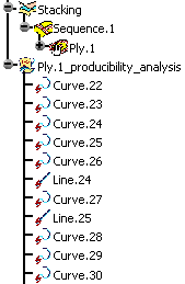
You can rely on those curves if you later want to create a dart or a splice in order
to lower the ply deformation.
Use the inspection points to create the limiting or splicing curves.
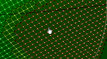
- We advise you to delete the
geometrical set containing the producibility curves
once you have created your limiting or splicing curves, as it will ease the processing of your model. - Make sure you create the limiting or splicing curves as data, in
order not to delete
them with the producibility curves.
-
Click Inspection to start the inspection of the producibility on the selected ply.
Note that the operating mode is the same as with the Producilibilty Inspection icon,
less the Create file from fields, as they are not necessary here.
-
Click OK to create a producibility parameters feature under the ply in the specification tree.
Parameters (i.e. seed point, warp and weft) are now stored and
may be later used when flattening plies.
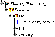
Therefore OK creates one producibility parameters feature under each selected ply.
In that case, a warning is displayed to advice you to modify the fiber simulation strategy.
Displaying the Flat Pattern
-
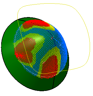
Select the Display Flat Pattern check box to preview the flatten shape of the ply or of the cut-piece to be displayed in the 3D viewer.

-
Click Apply to preview the flatten shape.
The seed point and the x and y axes of the rosette transferred at this seed point define the plane in which the flatten shape is positioned.
Checking the Material Width
The Check Material Width check box becomes available once you have selected Display Flat Pattern.
-
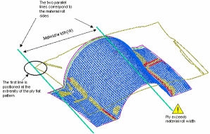
Select the Check Material Width check box to determine whether a ply or a cut-piece geometry fits into the given material width.

This is done as follows:
Two lines representing the material roll sides are displayed on the flat pattern of the ply.
The first line is positioned at the extremity of the flat pattern.
If the second line intersects the flat pattern, a warning is displayed.
If the flat pattern is larger than twice the material roll width, additional lines are displayed.
-
You can choose to check the material width along:
- the warp: the lines are perpendicular to the blue line of the transferred rosette,
- or along the weft: the lines are perpendicular to the red line of the transferred rosette.
- switching from one option to the other rotates the lines by 90 degrees.
-
Click Apply. A green or a red sign is displayed to indicate whether the flatten shape fits into the material roll width or not.
 or
or

Creating a Dart
-
Once an entity and a point have been selected, the
 button becomes available.
It starts the Dart command and deactivates temporarily the Producibility command. -
Once you are done with the dart creation, you will revert to the Producibility dialog box.
![]()