once you are satisfied with the Producibility analysis result of the seeds behavior.
Note that flatten shapes are not created on plies that contain cut-pieces.
You will:
![]()
Flattening Plies using one Location Point and Checking the Material Roll Width
-
Click Flattening
 .
.
The Flattening dialog box is displayed.
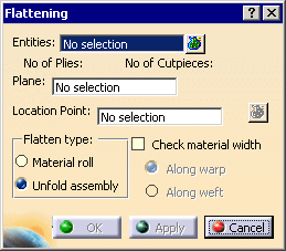
-
Select the feature you want to flatten.
It can be a ply, a ply sequence, a plies group or a stacking.
Click to select several plies (whether or not in the same group
of plies).
In our scenario, we have selected the stacking.
The number of plies and cut-pieces is computed.
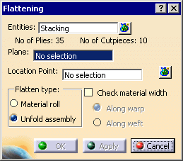
-
Select a plane as the flattening support.
Its name is displayed in the dialog box.
We have selected Plane.1. -
Select a Point in this plane.
If you do not select any point, a default location point is defined on the origin of this plane.
In our scenario, we have selected one point.
You can also select several location points.Should you need to create the plane or the location point,
right-click in the appropriate field and create the element you need.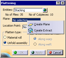

Refer to Generative Shape Design & Optimizer User's Guide for more information. -
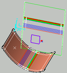
Select a Flatten type and click Apply to visualize the flatten shapes:
-
Material roll: the flatten shapes are positioned on the plane as they would be on a material roll,
that is, according to the fiber direction represented by the axis of the plane (default behavior).
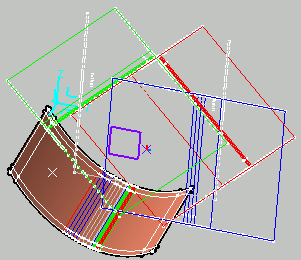
-
Unfold assembly: the flatten shapes are positioned on the plane according to the 3D positioning of the ply.
It can be used as a kind of unfolded definition of the Composites part.
-
-
If required, select the Check Material Width check box to determine whether a ply geometry fits into the given material width.

You can choose to check the material width:- along the warp: the lines are perpendicular to the blue line of the transferred rosette,
- or along the weft: the lines are perpendicular to the red line of the transferred rosette.
- switching from one option to the other rotates the lines by 90 degrees.
This is done as follows:
Two lines representing the material roll sides are displayed on the flatten shapes.
The first line is positioned at the extremity of the flatten shape.
If the second line intersects the flatten shape a warning is displayed but does not prevent the creation of the flatten shape.
If the flatten shape is larger than twice the material roll width, additional lines are displayed.
Click Apply to visualize the result of the check:
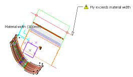
In addition, a red or green sign appears in the dialog box to indicate if the flatten shape fits into the material roll width or not.
 or
or  .
. -
Click OK. The flatten shape of the selected plies is generated using the producibility parameters
(seed point, warp and weft) stored under each ply, as well as the seed orientation.
Flatten curves are created, they lie on the support plane around the location point.
Each flatten curve corresponds to a a ply and the color code for their orientation is consistent with the one used when creating the plies.
In the specification tree:- each flatten curve corresponding to a ply is added to this Ply node.
- an exclamation mark identifies the plies exceeding the material width, if you have flattened them with the Check material width check box,
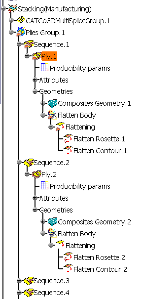
the plane field is already filled when you launch the Flattening command and all created flatten curves lie on this plane.
Selecting several Location Points
-
As Entities, select Ply.9, Ply.10, Ply.15 and Ply.16 for instance.
-
Select Plane.1.
-
Click Multiselection
 .
.
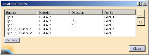
The Location Points dialog box is displayed.

-
Select the FlatteningPoints geometrical set in the specification tree.
Each point is automatically assigned to a ply.
-
Close the Location Points dialog box and click OK to validate.
The flatten plies are created.
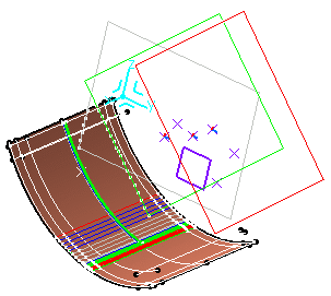
Editing a Flattened Ply
-
Right-click the stacking node.
-
Select Stacking object, then Hide/Show flatten contour.
The flatten curves are not displayed anymore.
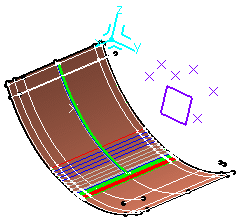
-
In the specification tree, go to Ply.1 node.
Right-click Flatten body and select Hide/Show.
The flatten contour of Py.1 is displayed.
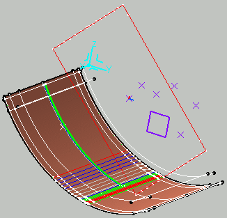
Double-click Ply.1 to edit it.
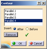
In the Geometry tab, the features composing the manufacturing geometry are displayed.- Add lets you create other features, a contour for example, via the Contour dialog box.
- Modify
lets you manually modify the contour geometry via the Contour dialog
box:
select other curves to form the closed contour. - Remove
lets you remove a contour or a curve composing the contour:
simply select the contour or curve and click Remove.
- In the Attributes
tab, the Material, Direction, and Rosette options are dimmed:
indeed they cannot be modified as you are in the Manufacturing work.
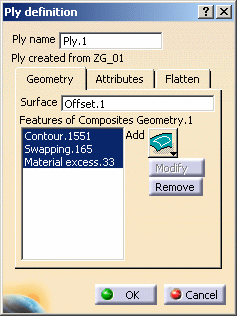
In the Flatten tab, you can select the flatten curve in the Flatten Geometry field,
and replace it with another one.

-
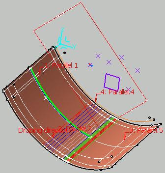
In the Ply definition dialog box, select the contour of Ply.1 to modify it.
-
Select the curves to define a new contour for Ply.1.
-
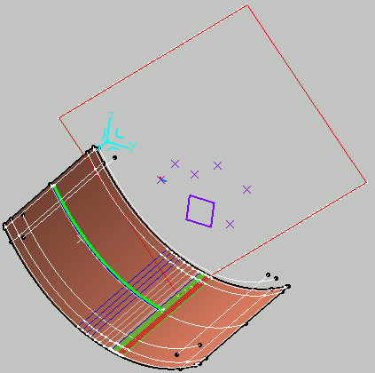
Click OK.
The flatten contour is updated.
-
Start the Generative Shape Design workbench.
-
Right-click Flatten Body and select Define in work object.
-
Click Curve Smooth
 .
.
The Curve Smooth Definition dialog box is displayed.

-
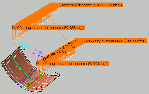
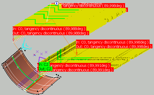
Select Flatten contour.1 as the curve to smooth.
Texts are displayed on the flatten contour showing the discontinuities before smoothing.
-
Click Preview to see how the flatten contour is to be smoothed.
You can see that several points on the flatten contour need to be refined.
-
Modify the parameters until you are satisfied with the smoothing of the flatten contour.
-
Click OK to validate.
The modified flatten contour is put in no show and a curve smooth feature is added to the specification tree.
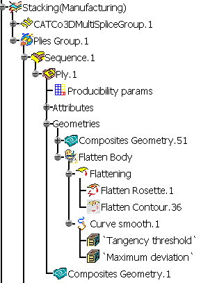
For more information, refer to the Smoothing Curves chapter in the Generative Shape Design & Optimizer User's Guide.
Features created under the flatten body are not supported. In such a case, the flatten contour is in show mode.
![]()