Selecting Relimited Curves
-
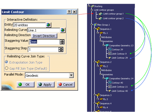
Click Limit Contour
 .
.
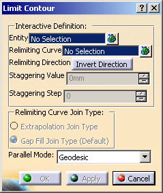
The Limit Contour dialog box is displayed.
-
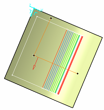
Select the entity where to insert the limit contour.
It can be a ply, a sequence, a plies group or a stacking.
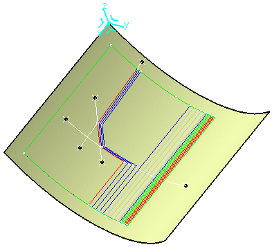
In our example we selected Plies Group.1.
Multi-selection of plies is possible. 
All plies must lie on the same surface. If some plies lie on various surfaces, a warning message is issued. -
To select the Relimiting Curves, click Multiselection
 .
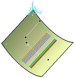
.The curve must lie on the same surface as the selected entity. If it lies on a other surface, a warning message is issued. Select Line.2 and Line.1 in the geometry and set the values as shown below.
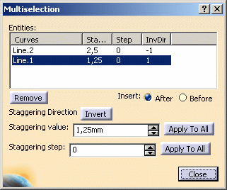
When entering the values for Line.2, click Invert, to change the material Staggering Direction.
A red arrow is displayed in the 3D geometry to show you the Staggering Direction.
-
Define the Staggering Step.
By default it is set to 0. Therefore, the staggering step for the first ply will be 0, 1 for the second ply, 2 for the third ply, and so on.-
This option is available whatever Entity you selected.
If you selected several plies, the step is automatically defined starting from the one you selected. -
This option is influenced by the order of selection of the plies. Be careful when selecting the plies.
-
-
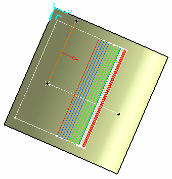
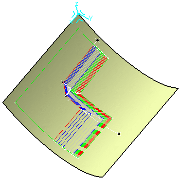
Close the Multiselection dialog box and select Extrapolation Join Type as option for the relimiting curve.
The relimiting curve is displayed with a red arrow showing the material that is to be kept.
-
The Limit Contour feature created is a parallel to the curve you have selected. You can select the type of parallel that will be created:
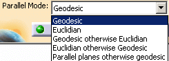
Geodesic and Euclidian impose the type you have selected.
Geodesic otherwise Euclidian will create a geodesic parallel if possible, otherwise it will create an Euclidian parallel.
Euclidian otherwise Geodesic will create an Euclidian parallel if possible, otherwise it will create a geodesic parallel.
Parallel planes otherwise geodesic will create an parallel planes if possible, otherwise it will create a geodesic parallel. -
Click OK.
Limit Contour on Cut-pieces
You can create a limit contour on cut-pieces.
-
Open the LimitContour4.CATPart document.
-
Click Limit Contour
. -
In the Limit Contour dialog box, click Multiselection
in the
Entity field. -
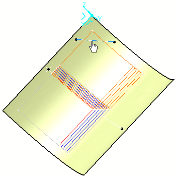
Select the cut-pieces as shown below:
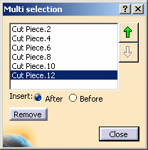
Then close the Multiselection dialog box. -
Click Multiselection
in the
Relimiting Curve field. -
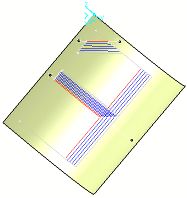
Select Line.2 in the geometry as relimiting curve.
-
Change the staggering direction by clicking Invert.
-
Close the Multiselection dialog box.
-
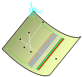
Change the relimiting direction by clicking Invert Direction.
-
Set the staggering value to 5mm.
-
Leave the staggering step to 0mm.
-
Click OK to validate.
- You can create a limit contour defined on only one curve and define the material Relimiting Direction using Invert Direction , as well as the Staggering Value.
- You can also select a knowledgeware parameter containing the
staggering value.
To do so, right-click the Staggering Value field and select Edit Formula. - The staggering value can be negative.
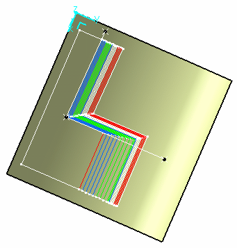
Selecting Non-Relimited Curves
 |
 |
-
Open the LimitContour2.CATPart document.
-
Click Limit Contour
. -
Select Plies.Group 1 as entity.
-
Click Multiselection
. -
Select Line.2 and Line.1 in the geometry and set the values as shown below.
-
Close the Multiselection dialog box and keep Gap Fill Join Type selected.
-
Click OK to create the limit contour.
Deleting Limit Contours
-
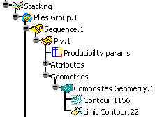
In the specification tree, right-click Ply.1.
-
Select Limit Contour object then Remove similar limit contours.
-
Select plies for which you want to remove the limit contour.
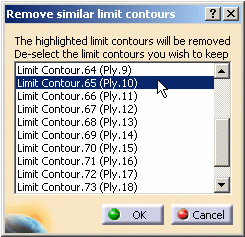
The Limit Contours displayed in the dialog box share the same input parameters (i.e. curves, staggering values, staggering directions etc.). -
Select Ply.10 to Ply.20 then click OK to apply your changes.
Using the After and Before options
-
Open the LimitContour3.CATPart document.
-
Click Creates a Limit Contour for a Ply
. -
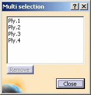
Click Multiselection
. -
Select Ply.1, Ply.2, Ply.3, and Ply.4 in the specification tree.
They are displayed in the multiselection dialog box.
-
Click Multiselection
. -
Select Line.2 and Line.1 in the geometry and set the values as shown below.
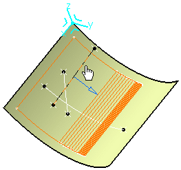
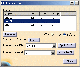
If you want to select Line.3, you must respect the order of selection of relimiting curves for the contour to be valid. In our example, the right order is Line.2, Line.3 and Line.1. -
Click Before, to insert Line.3 before Line.1 (or select Line.2 and click After).
-
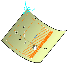
Select Line.3 in the geometry.
-
Set the values for Line.3.
-
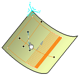
Click OK to create the limit contour.
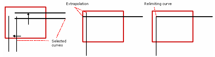
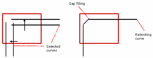
- The relimiting curve is defined by curves
joining each other in two ways:
- extrapolation, then relimitation
or - gap filling
- extrapolation, then relimitation
-
One limit contour is created per ply (if several plies were selected).
-
The limit contour can be used for variable ply staggering.
-
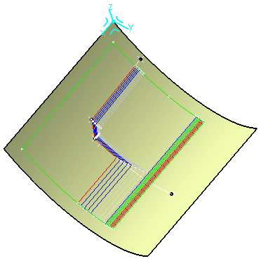
If the relimiting curve is modified or another one is selected, all limit contours sharing this curve are recomputed.
-
For each engineering ply, the inputs of the limit contour are stored and can be edited and modified.
![]()