Open the Lines1.CATPart document.
For instance, if you choose the Point-Point type, you are not able to select a line. May you want to select a line, choose another type in the combo list.
as input for support automatically. This support feature would not be transferred, if we change line type to Point-Direction.
Defining the line type
Point-Point
-
Click Line
 .
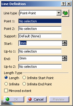
.The Line Definition dialog box is displayed. -
Select the Point-Point line type.
-
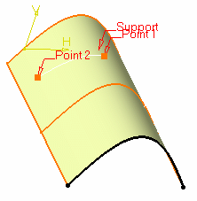
Select two points.
A line is displayed between the two points.
-
If needed, select a support surface.
In this case a geodesic line is created, i.e. going from one point to the other according to the shortest distance along the surface geometry (blue line in the illustration below).
If no surface is selected, the line is created between the two points based on the shortest distance.
If you select two points on closed surface (a cylinder for example), the result may be unstable. Therefore, it is advised to split the surface and only keep the part on which the geodesic line will lie. 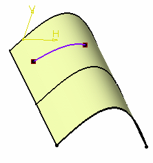
-
Specify the Start and End points of the new line, that is the line endpoint location in relation to the points initially selected.
These Start and End points are necessarily beyond the selected points, meaning the line cannot be shorter than the distance between the initial points. -
Check Mirrored extent to create a line symmetrically in relation to the selected Start and End points.

The projections of the 3D point(s) must already exist on the selected support. -
Click OK to create the line.
The line (identified as Line.xxx) is added to the specification tree.
Point - Direction
-
Click Line
 .
. -
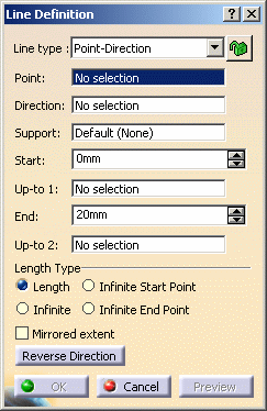
Select the Point-Direction line type.
-
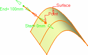
Select a reference Point and a Direction line.
A vector parallel to the direction line is displayed at the reference point.
Proposed Start and End points of the new line are shown.
-
If needed, select a support surface. In this case a geodesic line is created, i.e. the direction of the
created line corresponds to the projection of the given direction onto the support. -
Specify the Start and End points of the new line.
The corresponding line is displayed. 
-
Click OK to create the line.
The line (identified as Line.xxx) is added to the specification tree.
Angle/Normal to curve
-
Click Line
 .
. -
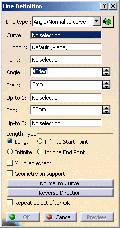
Select the Angle/Normal to curve line type.
-
Select a reference Curve and a Support surface containing that curve.
- If the selected curve is planar, then the Support is set to Default (Plane).
- If an explicit Support has been defined, a contextual menu is available to clear the selection.

We advise you to avoid the creation of lines when the direction does not lie on the support, as well as the edition of the angle between the direction and the support in such cases. -
Select a Point.
-
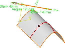
Enter an Angle value.
-
Specify the Start and End points of the new line.
The corresponding line is displayed. -
Check Repeat object after OK if you wish to create more lines with the same definition as the currently created line.
In this case, the Object Repetition dialog box is displayed, and you key in the number of instances to be created before pressing OK. 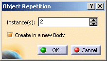
As many lines as indicated in the dialog box are created, each separated from the initial line by a multiple of the angle value. 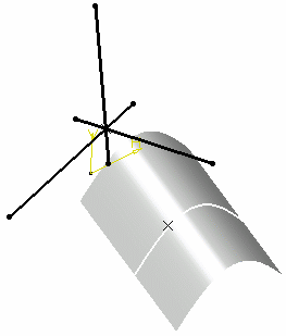
You can check Geometry on Support if you want to create a geodesic line onto a support surface.
The figure below illustrates this case.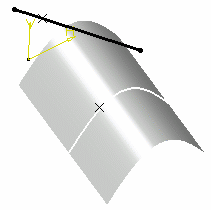
Geometry on support option not checked 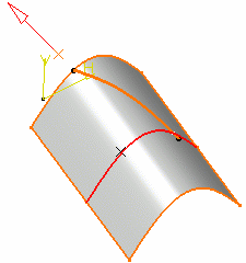
Geometry on support option checked 
This line type enables to edit the line's parameters. Refer to Editing Parameters to find out more. -
Click OK to create the line.
The line (identified as Line.xxx) is added to the specification tree.
Tangent to curve
-
Click Line
 .
. -
Select the Tangent to curve line type.
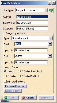
-
Select a reference Curve and a point or another Curve to define the tangency.
- if a point is selected (mono-tangent mode): a vector tangent to the curve is displayed at the selected point.
- If a second curve is selected (or a point in bi-tangent mode),
you need to select a support plane. The line will be tangent to
both curves.
- If an explicit Support has been defined, a contextual menu is available to clear the selection.
When several solutions are possible, you can choose one (displayed in red) directly in the geometry, or using the Next Solution button. 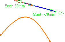

Line tangent to curve at a given point Line tangent to two curves -
Specify the Start and End points to define the new line.
-
Click OK to create the line.

In the image above we select a curve and a point as Element 2.The line (identified as Line.xxx) is added to the specification tree.
Normal to surface
-
Click Line
 .
. -
Select the Normal to surface line type.

-
Select a reference Surface and a Point.
-
Specify Start and End points to define the new line.
The corresponding line is displayed. 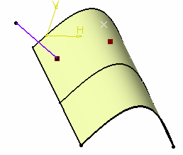
-
Click OK to create the line.
The line (identified as Line.xxx) is added to the specification tree.
Bisecting
-
Click Line
 .
. -
Select the Bisecting line type.
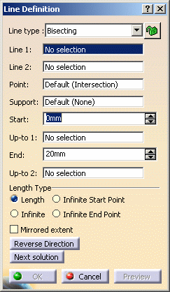
-
Select two lines. Their bisecting line is the line splitting in two equals parts the angle between these two lines.
-
Select a point as the starting point for the line. By default it is the intersection of the bisecting line and the first selected line.
-
Select the support surface onto which the bisecting line is to be projected, if needed.
-
Specify the line's length by defining Start and End values (these values are based onto the default start and end points of the line).
The corresponding bisecting line, is displayed. -
You can choose between two solutions, using the Next Solution button, or directly clicking the numbered arrows in the geometry.
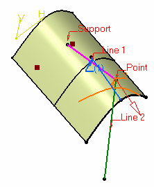
-
Click OK to create the line.
The line (identified as Line.xxx) is added to the specification tree.
- Regardless of the line type, Start and End values are specified by entering distance values or by using the graphic manipulators.
- Start and End values should not be the same.
- Check the Mirrored extent option to create a line symmetrically in relation to the selected Start point.
It is only available with the Length Length type.- In most cases, you can select a support on which the line is to be created. In this case, the selected point(s) is projected onto this support.
- You can reverse the direction of the line by either clicking the displayed vector or selecting the Reverse Direction button (not available with the point-point line type).
Parameters can be edited in the 3D geometry. For more information, refer to the Editing Parameters.
You can isolate a line in order to cut the links it has with the geometry used to create it. To do so, use the Isolate contextual menu. For more information, refer to the Isolating Geometric Elements.
You cannot create a line of which points have a distance lower than the resolution.
Creating a line up to an element
It is available with all line types, but the Tangent to curve type.
Up to a point
- Select a point in the Up-to 1 and/or Up-to 2
fields.
Here is an example with the Bisecting line type, the Length Length type, and a point as Up-to 2 element. 
Up to a curve
- Select a curve in the Up-to 1 and/or Up-to 2
fields.
Here is an example with the Point-Point line type, the Infinite End Length type, and a curve as the Up-to 1 element. 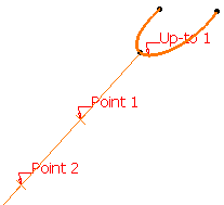
Up to a surface
- Select a surface in the Up-to 1 and/or Up-to 2
fields.
Here is an example with the Point-Direction line type, the Length Length type, and the surface as the Up-to 2 element. 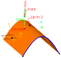
- If the selected Up-to element does not intersect with the line being created, then an extrapolation is performed. It is only possible if the element is linear and lies on the same plane as the line being created.
However, no extrapolation is performed if the Up-to element is a curve or a surface.- The Up-to 1 and Up-to 2 fields are grayed out with the Infinite Length type, the Up-to 1 field is grayed out with the Infinite Start Length type, the Up-to 2 field is grayed out with the Infinite End Length type.
- The Up-to 1 field is grayed out if the Mirrored extent option is checked.
Defining the length type
- Select the Length Type:
- Length: the line will be defined according to the Start and End points values
- Infinite: the line will be infinite
- Infinite Start Point: the line will be infinite from the Start point
- Infinite End Point: the line will be infinite from the End point
By default, the Length type is selected.
The Start and/or the End points values will be grayed out when one of the Infinite options is chosen.
Reselecting automatically a second point
This capability is only available with the Point-Point line method.
-
Double-click Line
 .
.The Line Definition dialog box is displayed. -
Create the first point.
The Reselect Second Point at next start option appears in the Line Definition dialog box. -
Check it to be able to later reuse the second point.
-
Create the second point.
-
Click OK to create the first line.
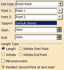
The Line Definition dialog box opens again with the first point initialized with the second point of the first line. -
Click OK to create the second line.
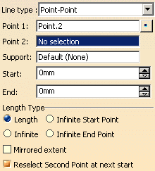

To stop the repeat action, simply uncheck the option or click Cancel in the Line Definition dialog box.
![]()
