| |
|
Operator |
Type |
Sub- Type |
Parameter(s)
displayed |
|
Bump |
|
|
Deformation Distance
(Maximum distance along the deformation direction from the deformed
surface) |
|
Circle |
Center and Radius |
|
Radius, Start Angle, End Angle |
|
Center and Point |
|
Start Angle, End Angle |
|
Two Points and Radius |
|
Radius |
|
Bitangent and Radius |
|
Radius |
|
Center and Tangent |
Curve as center element |
Radius |
|
Corner |
|
|
Radius |
|
Curve Parallel |
|
Geodesic parallel mode |
Constant
(Offset Distance) |
|
Diabolo |
|
|
Draft Angle |
|
Extrapolate |
Length |
|
Length, Limit Type |
|
Extrude |
|
|
Length 1, Limit 1
Length 2, Limit 2 |
|
Helix |
|
|
Taper Angle, Starting Angle
Pitch
Height |
|
Line |
Angle/Normal to Curve |
Support and Geometry on support selected |
Angle
Length (Start and End) |
|
Point-Point |
Support selected |
Length (Start and End)
Infinite Start Point: End
Infinite End Point: Start
Infinite: / |
|
Point-Direction |
Support selected |
|
Tangent to Curve |
Mono-tangent and Support selected |
|
Normal to Surface |
|
|
Bisecting |
Support selected |
|
Offset |
|
|
Offset Value |
|
Plane |
Angle/Normal to Plane |
|
Angle |
|
Offset from Plane |
|
Length, Offset Distance |
|
Point |
Coordinates |
|
Length, X, Y, Z coordinates |
|
On Curve |
Geodesic |
Length (distance on curve) |
|
On Plane |
|
Length, H, V |
|
On Surface |
|
Length (distance on surface) |
|
Polyline |
|
|
Radius, Radius at point |
|
Reflect Line |
|
|
Angle |
|
Revolve |
|
|
Angle1, Angle2 |
|
Rotate |
|
|
Rotation Angle |
|
Shape Fillet |
Bi-Tangent Fillet |
|
Radius |
|
Sphere |
|
|
Parallel Start Angle, Parallel End Angle, Meridian
Start Angle, Meridian End Angle |
|
Radius |
|
Spiral |
|
Angle and Radius |
|
Start Radius
End Radius
End Angle |
|
Angle and Pitch |
|
Start Radius
Pitch
End Angle |
|
Radius and Pitch |
|
Start Radius
End Radius
Pitch |
|
Sweep |
Explicit Sweep |
|
Angle |
|
Linear Sweep |
Two Limits |
Length1, Length2 |
|
With Reference Surface |
Angle, Length1, Length2 |
|
With Reference Curve |
Angle, Length1, Length2 |
|
With Draft Direction |
Angle, Length1, Length2 |
|
Translate |
Distance and Direction |
|
Distance |
|
 |
-
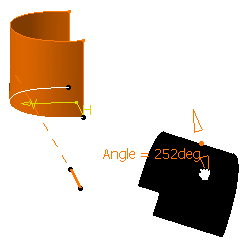
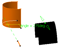
Once you selected the inputs to create the rotated
element, click Preview to display the associated parameters
in the 3D geometry.
-
Double-click the angle value in the 3D geometry.
| The Edit Parameter dialog box appears. |
 |
-
Use the spinners to modify the value.
| The display automatically updates and the object is
modified accordingly. |
| You can modify the angle value using the Angle
manipulators. |
 |
 |
-
To display the parameters' values, you need to
click the Preview button. Otherwise, only manipulators
are displayed.
-
To edit the parameters once the feature is
created, select it in the specification tree, right-click
xxx.1object > Edit Parameters from the contextual menu.
-
If you want the parameters to be kept
permanently, check the Parameters of features and constraints
option in Tools > Options > Infrastructure > Part
Infrastructure > Display.
|
|


