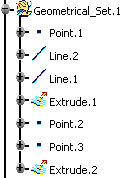
You will find other useful information in the Managing Groups and Hiding/Showing chapters.
- You can insert and manipulate geometrical sets in the specification tree in much the same way as you manage files in folders. For instance, you can copy/paste elements from a geometrical set to a target geometrical set.
- These management functions have no impact on the part geometry.
- When loading the Generative Shape Design workbench, a Geometrical Set
automatically becomes the current body.
This also means that only the results of the Hybrid Body, i.e. the result of all the operations performed on geometry, is visible and not any intermediate state of the Hybrid Body. - You can define the Generative Shape Design feature that is to be seen when working with another application, such as Generative Structural Analysis for example.
- When opening a document, features are visualized depending on their order in the specification tree. After a modification, the order is no longer respected; therefore the visualization may be different.
To do this, while in the Generative Shape Design workbench:
- Choose Tools > External View... from the menu bar.
The External View dialog box is displayed. .
- Select the element belonging to a Geometrical Set that should always been seen as the current element when working with an external application.
- Click OK in the dialog box.
The selected element will be the visible element in other applications, even if other elements are created later in the .CATPart document, chronologically speaking. To check whether an external view element has already been specified, choose the Tool > External View... menu item again. The dialog box will display the name of the currently selected element. This also allows you to change elements through the selection of another element. Note that you cannot deselect an external view element and that only one element can be selected at the same time.
You can also open the GeometricalSets2.CATPart document.
Inserting a Geometrical Set
-
In the specification tree, select an element as the location of the new geometrical set.
This element will be considered as a child of the new geometrical set and can be a geometrical set or a feature. -
Select Insert > Geometrical Set... from the menu bar.

The Insert Geometrical Set dialog box is displayed. The Features list displays the elements to be contained in the new geometrical set. -
Use the Father drop-down list to choose the body where the new geometrical set is to be inserted. All destinations present in the document are listed allowing you to select one to be the father without scanning the specification tree. They can be:
-
geometrical sets
-
parts
-
Bodies (not hybrid)
-
-
Select additional entities that are to be included in the new geometrical set.
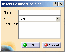

If all selected entities belong to the same geometrical set, the father of the new geometrical set is automatically set to the father of these entities. -
Click OK to create the geometrical set at the desired location.
Removing a Geometrical Set
- If you want to delete the geometrical set and all its contents:
-
Right-click the geometrical set then select the Delete contextual command.
- If you want to delete the geometrical set but keep its
contents:
This is only possible when the father location of the geometrical set is another geometrical set. This is not possible when the father location is a root geometrical set.
-
Right-click the desired geometrical set then select the Geometrical Set.x object > Remove Geometrical Set contextual command.
Moving a Geometrical Set to a New Body
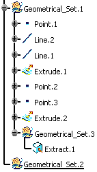
Here we moved GeometricalSet.3 last in GeometricalSet.1.
-
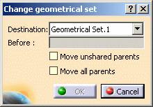
From the specification tree, select the geometrical set then choose the Geometrical Set.object > Change Geometrical Set... item from the contextual menu.
The Change geometrical set dialog box is displayed, listing all the possible destinations. 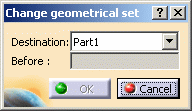
-
Select the Destination body where the geometrical set is to be located.
-
Click OK to move the geometrical set to the new body.
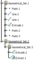
The geometrical set is moved to its new location in the specification tree, but geometry remains unchanged. 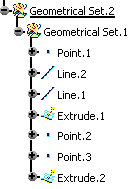
Moving Elements of a Geometrical Set to a New Body
-
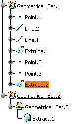
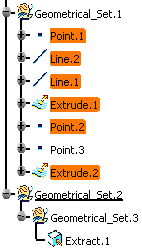
From the specification tree, select the element(s) (here Extrude.2) then choose the Extrude.2 object > Change Geometrical Set... item from the contextual menu.
-
Select the Destination body where the geometrical set is to be located.
-
Select the element above which the one you already selected is to be inserted.
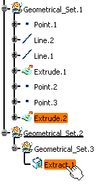
You can directly select this positioning element. In this case the Destination field is automatically updated with the body to which this second element belongs. -
Click OK to move the elements to the new body.
Sorting the Contents of a Geometrical Set
-
Right-click Geometrical Set.1 from the specification and choose the Geometrical Set.1 object > AutoSort command.
Instantly, the contents of the Geometrical Set are reorganized to show the logical creation process.
The geometry remains unchanged.
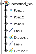
Reordering Elements within a Geometrical Set
-
Right-click Geometrical Set.1 from the specification tree and choose the Geometrical Set.1 object > Reorder Children command.
The Reorder Children dialog box is displayed. -
Select an element.
-
Use the arrows to move an element up or down.
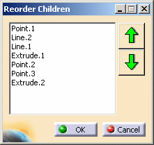

When the first element of the list is reordered upward, it becomes the last element. Similarly, when the last element of the list is reordered downward, it becomes the first element.
Dragging and Dropping Elements
Replacing Features
Refer to the Replacing or Moving Elements chapter in the Part Design User's Guide.
![]()

